Category Archives: Hardware

Quick Test of Geophone Response

I just wanted to post a quick article about geophones.  Geophones are essentially instruments that allow us to measure the velocity or acceleration of the ground.  Yes, seismometers do this, but generally when we refer to geophones we are talking about single sensor (almost always vertical sensing) devices used for seismic imaging in oil/gas exploration.  I've talked about seismic surveys before (here for example). The "element", or the actual sensor is pictured below.  These sensors have a magnetic element on a spring inside a coil of wire.  Motion of the magnet (resulting from ground motion) generates a small electrical potential in the coil.  If I can find a cheap element/case on eBay I'll do a teardown of one in the future.  The signal generation happens through a process called "electromagnetic induction", described by Michael Faraday in 1831!  Want to know more about induction? Head over to the wikipedia page or shout out and we can put together a demonstration.

Dr. Ammon, whose office is next door, brought over an old element that he wanted to compare with our seismometers in the basement of the building.  Not knowing the output voltage range well, we hooked it up to a Rigol DS1102E oscilloscope on my desk.  I set the trigger of the oscilloscope (when it started collecting data) to just above ground potential so that any appreciable motion will trigger data recording.  We recorded the voltage output of the sensor about 6800 times per second!

The sensor element from a geophone.  (Image: Ebay)

Below is the waveform collected from hitting my desk with moderate force.  Surprisingly these elements put out +/-4 Volts! When shaking the element to it's limits we were seeing voltages of around +/- 10 Volts.  To me this indicates there are many turns in the coil and a very strong, probably rare earth, magnet inside.  Measurement of the coil resistance or a teardown will tell if this is correct! I've also included the power spectral density for those of you interested.  These figures tell us about the frequency response of the instrument.  Depending on how the spring system is setup, the oscillator is very sensitive to some frequencies and not so sensitive to others.  These diagrams help us characterize this response.  

Collected waveform from hitting my desk.
Power Spectral Density

Power Spectral Density: Zoomed in

Sorry for the short post, but I just wanted to share a quick desktop experiment!

The Infrasound Bucket - Part 1 - Hardware

I'd like to write a short series of posts describing my setup of the infrasound unit I've written about before.  This is the same unit we used to look at traveling acoustic energy from the Russian meteorite and will soon use to examine earthquakes! Placing the unit inside my office or even inside the apartment proved to be very noisy as I saw every time someone opened or closed a door!  The makers (Infiltec) suggested that I put it outside, maybe in a drink cooler to shield it from the weather.  I did exactly that (photos below), but the cooler turned out to not be water proof and had about 2 cm water standing in the bottom when I checked it after a small storm.  The data quality while the instrument was outside was amazing though, with seismic signals coming through very clearly.  It was time to design a new system that would: 1) Be safe to leave outside in the weather, 2) Not have thick data cables running inside to a computer, 3) Would not require an inside computer, and 4) Would automatically post the current data online.

For the first post we're going to talk about the casing setup and mounting of all the vital hardware.  One weekend we decided to go wandering about Home Depot to find a suitable shell for the instrument as well as pickup a few other essential supplies.  Lendi had the flash of inspiration that we should use a 5-gallon plastic bucket... the ones at the Home Depot "Homer's All Purpose Bucket" even have an O-ring seal on the lid.  Perfect.

A built in O-ring seal on the bucket.

Now to figure out how to hold the hardware up off the bottom of the bucket.  In an ideal world this isn't needed, but in reality water may get in and I don't want it covering electronics thrown in the bottom of the bucket.  We used 1/4" plywood cut to a keystone shape that just fits the vertical profile of the bucket.  Adding two "L" brackets from the shelving section meant for ~$15 we had the shell and left over plywood.
Test fitting the plywood into the bucket.  Notice the cooler in the background that formerly housed the instrument.

I bolted the infrasound unit to the wood by using "plumber's tape" or metal strap with holes down its length.  This isn't the most elegant solution, but it meant no drilling the infrasound case which is semi-sealed on its own.  It is also very easy to get the unit out for any maintenance.   My RaspberryPi ended up having problems on the circuit board, so I've bolted a Beagle Bone Black to the board as well.

Front of the mounting board.  Infrasound unit (right), Beagle Bone (left), and power plugs (top left).

Rear of the mounting board with power passthrough.  

With no tall standoffs handy I made use of locking nuts, washers, and other assorted 4-40 hardware.

Two holes were drilled in the side of the bucket: one for the power and one for the air tube to the infrasound instrument.  I passed the power cable through (outdoor zip cord) through as well as clear plastic tubing and sealed it with bathroom silicon sealant.  I'd recommend sealing on the inside and outside of the bucket bulkhead.  Make sure to leave extra cable and tube for drip loops. A drip loop like structure was fashioned on the outside of the bucket to ensure no rain would blow up the tube into the unit.  We taped the tube down and then ran beads of silicon to secure it to the bucket.  After the sealant dried we moved the tape and secured the rest of the tubing.

Power and air tube sealed into the bucket and loops to prevent water flow.

Inside the bucket: notice the power plug.

In later posts we'll talk about how the power is actually provided and such, but the part that pertains to the hardware is the mounting of two binding posts on the plywood at the standard 3/4" spacing.  This allows us to power the board from a banana jack on the bench for testing or operationally in the bucket.  I drilled a passthrough hole to send power from the back of the jacks to the front of the panel.

Initially I built a 5V regulator to power the computer with from an LM7805 linear voltage regulator, but this was indeed a poor choice.  Even with a decent heat sink, the chip still got blistering hot when I was drawing 700mA (of the 1000mA rated power).  Considering this would be outside in the summer heat and the fact that I didn't want the failure point of a mechanical fan I decided to use a buck voltage converter.  Linear regulators dissipate all extra power as heat.  For example: I was feeding 12VDC to the converter with a 700mA load running at 5VDC.  That means that (12V-5V)*0.7 = 4.9 Watts of power was being turned into waste heat! No wonder, remember we think of watts as energy/time (Joules/second actually).  That's a lot of wasted electricity and really just a complication to our design, but it was very clean power.

The old linear regulator.  It's now awaiting a new use in the parts bin.

The buck converter is a switching type regulator.  I don't want to get into how switching regulators work current, but it's an interesting topic and you should have a read on the theory if you like.  I bought a small unit (P/N 1385) from Adafruit that is rated to 3A (though it gets warm there).  The power isn't quite as clean from this switching supply, but it's fine for out use here.  It works great with the Beagle Bone and provides lots of extra power for 5V accessories.  Don't want to order and ship from Adafruit? You can get the exact same thing from a model shop.  They are called "battery eliminator circuits" and allow modelers to plug their airplane, car, etc servo electronics (5VDC operation) into a 12V battery they already have in their kit.  Just clip the 3 pin servo plug off the end and you are ready to go.  Don't forget good soldering practice and to use heatshrink tube! Shorts could spark a fire, which we don't want.

The "battery eliminator circuit" or my 5V buck converter to supply 5VDC to the Beagle Bone.

So there it is! Next time I'm going to talk about setting up the power and network infrastructure.  Maybe even the serial communications! We're going to try to avoid using a serial-USB converter since the Bagle Bone has only one USB port (that I'm using for a WiFi adapter), I don't want to use a hub, and it's a chance to learn about signal level shifting and wire into that temping header on the board.

Everything fit into the bucket nicely and powers up from the bench power supply.

Chelyabinsk Meteorite - Infrasound, Seismic, and Satellites oh my!

Just as Earth was about to have a close encounter with asteroid 2012 DA14, the people of Chelyabinsk, Russia had a personal experience.  Before we talk about both 2012 DA14 and the Chelyabinsk event some terminology needs to be set out.  A meteoroid is a small chunk of debris in space, generally anything from a fleck of dust to a small boulder.  A larger space bit of debris is termed an asteroid.  A meteor is when some of this debris enters our atmosphere, heating up due to friction.  A meteor is called a meteorite if it actually reaches the surface of the Earth and survives impact.  Everyday we are pelted with many tiny meteors, but few reach the surface.  Most meteorites are never discovered as they are statistically much more likely to land in the ocean due to it's coverage of Earth's surface.  Sometimes meteorites are found on land, in fact it is common for scientists to go to Antarctica to look for the dark rocks on the surface of a white sheet of ice.  There are many pages on hunting meteorites  and a book as well, it's worth reading about if your curious how we find rocks that landed a long time ago.

It's worth saying that there are different kinds of space debris, some more stony, some made of almost solid metal, and some of ice.  While it's worth discussing, I'd rather focus on the current events in this post, so if you are curious there is a nice page at geology.com that gives the basics.

To begin, lets talk about 2012 DA14, or the non-intuitive name that we gave a near Earth asteroid that is about 160 feet in diameter and weighs a massive 190,000 metric tons.  This asteroid could do some serious damage and was scheduled to have a close call with Earth on February 15th.  How close? Well, it would be about 17,200 miles from the surface, which seems like a long way.  It's not.  The moon is 250,000 miles away (roughly) and we've been there and back in a matter of a few days.  In fact, the geosynchronous satellites that beam TV and weather data down to Earth orbit about 22,236 miles above the surface to rotate at the same rate the Earth does.  As shown in the figure below, 2012 DA14 passed between us and the geostationary satellite band; a very close call.

Why talk about 2012 DA14 in a post about a meteor over Russia? To say they are not related in any way.  They approached from entirely different directions and it just happened to be a coincidence of space and time.

Now for the event in Russia.  At 3:20:26 UTC on Feburary 15th a large meteor about the size of a schoolbus entered the atmosphere.  The 49-55 foot estimated diameter object probably weighed about 7000-10000 tons.  While heating up upon atmospheric entry the meteor "detonated" or exploded in mid-air.  This has happened before, a list of historic airbursts can be found here.  The most famous being a large explosion (also over Russia) in 1908 called the Tunguska event.  That explosion released the energy of 10-15 million tons of TNT, leveling forests and destroying an area of about 830 square miles.  The event that just occurred was about 500 kilotons of TNT equivalent, or roughly 20 times smaller.  Shock waves from the event still managed to send around 1500 people to local hospitals with shards of glass and building materials in their faces/skin from rushing to a window too see what was happening.  Videos of the entry are all over the web, in several you can hear the detonation and shock wave.

So how do we know so much about this object considering we didn't know anything about it until it exploded overhead? Well, remote sensing helps us.  When a meteor entered over Wisconsin in 2010, I wrote about following the trail on the US Doppler Radar Network (here).  This time we could see the meteor from weather satellites (Meteosat 10 image below) as well as on seismic and infrasound stations.  Another meteosat also captured several frames that have been made into a video here.  Current estimates of the entry speed are in the area of 40,000 mph with a very shallow entry angle.

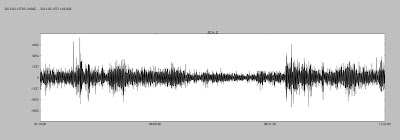
First the seismic observations.  So far I've seen reports of the Borovoye, Kazakhstan station seeing a gorgeous signal (thanks to Luke Zoet on this one). The station details, and even a photo are available at the USGS network operations page.  Below is a filtered (0.15 Hz low-pass) seismogram from BRVK.  This would be a result of the shock wave rattling the ground and seismic station.

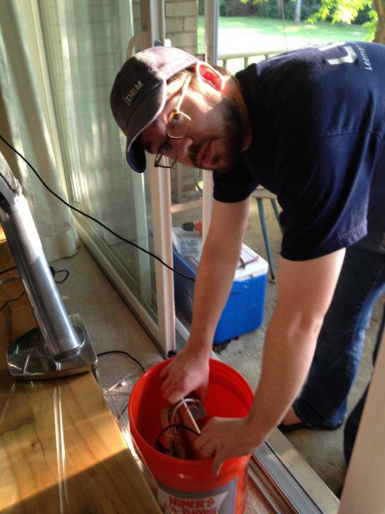
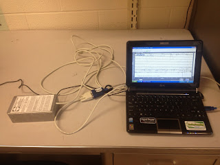
Next, and rather interesting, are the infrasound observations.  Infrasound is very low frequency sound (below 20Hz) that we can't hear, but can record as air pressure variations.  It so happens that Steve Piltz of the Tulsa National Weather Service has a microbarograph.  Upon seeing his data from an earlier earthquake (yes, ground movement causes air pressure waves), I immediately bought a unit from Infiltec and set it up in the office at Penn State.  Below is a picture of the station.

Infrasound propagation is incredibly complex and difficult to predict over such long distances, so I've done a simple calculation that is very likely going to be revised upon some discussions with seismologists this week.  First, I wanted to know how long the sound would have to travel.  To find the shortest travel distance between a latitude and longitude set you can assume a spherical Earth (not too bad for such a back of the envelope calculation) and some math.  Remember trigonometry? Well when it's modified to work on a sphere instead of in a plane it's creatively called 'spherical trigonometry' and consists of a strange function called the haversin.  If you are curious about how I calculated the travel path of the sound waves checkout the wikipedia page on the Haversine formula, but I've included the formula below.  Below is the result of the calculation, a great circle path between Chelyabinsk and State College, PA.
d = 2 r \arcsin\left(\sqrt{\operatorname{haversin}(\phi_2 - \phi_1) + \cos(\phi_1) \cos(\phi_2)\operatorname{haversin}(\lambda_2-\lambda_1)}\right)

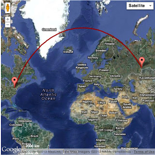
The distance the wave would travel would be something like 8670 kilometers.  Sound travels at 340.29 m/s at sea level, but since we're making assumptions we'll say 300 m/s is a nice number.  So the wave would take somewhere in the 7-8 hour range to reach State College (assuming it's non-dispersive and many other likely not so great assumptions).  Luckily for us, the event and the arrivals are overnight.  During the day my infrasound station is swamped by signals from office doors opening and closing amongst other things.  The meteor entered the atmosphere at 10:20 pm local time, so I've plotted the infrasound from 10 minutes before the meteor entered to well after the energy should arrive.  There is a large increase in the noise shortly after entry, but this is too soon.  Could it be seismic energy or arrival of a faster shock path? Maybe, that's a point for some discussion and revision later.  The big thing to notice is the noise increase at about 7-8 hours after the entry.  It's still early in the morning, so it is doubtful that this is people coming into work.

I've made a .SAC (seismic analysis code) file of the raw data for about 24 hours around the event available to download here.  Download the file (~19Mb) and play with it! The data is collected at 50Hz, but all that is in the meta-data (as well as location details).  I use ObsPy to do most of my analysis in Python, but you could use SAC or other codes meant for seismic event analysis.

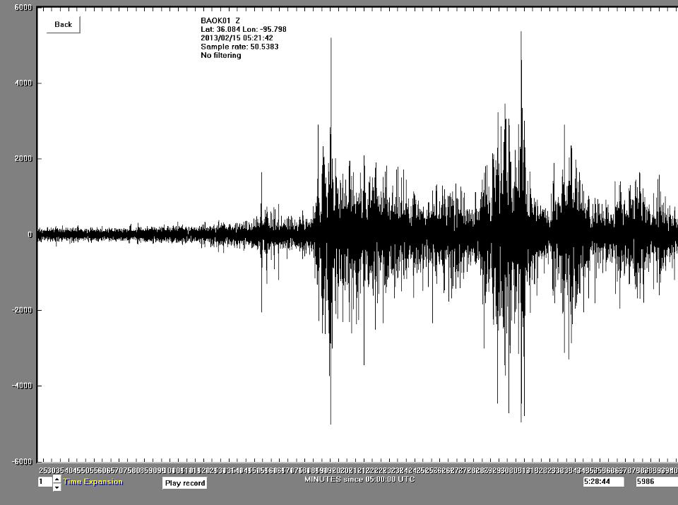
Steve's station in Oklahoma recorded similar signatures.  His data over a slightly shorter time span (5:21-11:42 UTC) is below, showing similar signatures.

Infrasound is actually what allows us to determine the energy release from the explosion.  As it turns out seismic stations and infrasound have been used to monitor nuclear testing for years (a relevant topic currently considering the recent tests by North Korea).

Overall, I'd say stay tuned for any updates.  Eventually the infrasound station I have will be setup for live streaming.  I'm sure after discussion with some folks more versed in infrasound travel we can clean up the data and maybe do some more back of the envelope energy/rate calculations for demonstation purposes.

Fluxgate Magnetometer Wrap-Up (For now)

Per lots of emails and requests I’m going to post what I have from the design of the fluxgate magnetometer mentioned in several previous posts (like this one).  The schematic attached at the bottom is a rough draft, but should provide some guidelines for designing and building a version of this instrument.  I’ve also attached links to several PDFs that I found very helpful when building this demo.

It should be noted that this design doesn’t have a plain readout with XXXXXX nT magnetic field, but displays a waveform on the oscilloscope.  Could one be made? Absolutely! Since this was more of a demonstration of the underlying physics I didn’t bother, but it would be a good weekend project.

First off let me list a few things I would build differently were I building this again:

-       Use shielded lead wires to reduce crosstalk to the coil.

-       Use a simple Analog-to-Digital converter so this output is projected from a laptop to the classroom screen (much easier than gathering students around an oscilloscope).  I think an Arduino might do the trick.  Raspberry Pi would be a good choice too.

-       Add gain adjustment knobs to the control panel.

-       I would again use the Velleman kit for the signal generator instead of re-designing the wheel.

When using this in the classroom I laid it alongside commercial magnetometers on the table.  We discussed the physical principles behind the instrument, and then students would use the demo fluxgate to generate an output wave.  Afterwards we used the commercial magnetometers to do simple tasks like finding conduits and keys. 

It would also be nice to have a first-principles proton-precession magnetometer.  There is a book “Signals from the Subatomic World: How to Build a Proton PrecessionMagnetometer” that describes one such instrument, but significant improvements in the instrument could be made with modern programming languages and ADC devices. 

I still welcome questions on the fluxgate and will probably update the instrument next time I teach an Intro Geophysics course (undetermined).  Thank you for all the interest and if you build one, please send your results and we’ll put them up here for all to benefit.  

3D Printing in the Lab - Will Lab Hardware Follow Software into Open-Source?

Today I read the article "Building Research Equipment with Free, Open-Source Hardware" by Joshua Pearce from a recent Science Perspectives section.  I'd like to share some thoughts on the article as I thought it introduced what may be the next "want" item in many labs.

In the modern scientific lab there is a large assortment of sophisticated hardware necessary to conduct increasingly complex research.  Generally scientific hardware is some combination of turn-key or off the shelf equipment and equipment designed and built in house.  In recent years laboratory software has progressively become part of the free and open-source software (FOSS) movement; hardware is now following the same trend with the advent of open-source 3D printers from the hobbyist community.

Open-source hardware became popular in the late 90’s with the basic stamp “board of education” microcontroller circuit boards, but the Arduino has taken over the hobby market with its $30 price tag.  Arduino has a number of modules, or shields as they are called, ready built with significant code libraries available.  With the Arduino circuit boards scientists can perform basic hardware control with digital and analog outputs in addition to basic analog-to-digital conversion.  

The RepRap open-source 3D printer is driven by the Arduino and can be constructed for <$1000.  The machine prints the parts required to make another RepRap printer, so building a machine is approached by entering the RepRap community with a parts request.  Users also post 3D designs on Thingiverse for download and printing by anyone.  A sufficient amount of laboratory equipment from test tube racks and filter wheels to Dremel tool adapters are already online.  

Printing laboratory equipment may not only reduce the cost of research, but allow the same flexibility, innovation, and rapid development cycle enjoyed by scientific software.  Being able to create a custom bracket, holder, mold, or sample jig could be advantageous to almost any laboratory and allow research to be conducted more efficiently with less focus on coordinating development with engineers at commercial manufacturers.  The open-source nature of the parts library will reduce duplication of work between those in a common field of research and allow cross-lab standardization of sample preparation techniques.  

There are limitations to what can be easily constructed in the lab, such as 3D printing with metal.  The technology to do this exists, but is too complex and expensive at the present time for individual applications.  While working at Oak Ridge National Laboratory I got the opportunity to see 3D printing with titanium.  The video below is a titanium ball... bouncing. (Apologies for the portrait video and quality, this was taken several years ago with an early iPhone.)


Like all community projects, the RepRap is being updated to have greater capabilities.  According to the project website a major milestone will be printing with electrical conductors to manufacture rapid prototype circuit boards without milling away copper clad board material.  

Just as sometimes labs must use commercial software, it is likewise not expected that all lab hardware will become open source.  Some tolerances are too tight for the parts to be constructed by simple printers and some materials are not practical to print in the lab.  With all this in mind it is worthwhile to monitor the progress of open-source hardware such as the RepRap, Arduino, and the new RaspberryPi single board computer.  These tools may provide teaching support also as controlling and displaying data from classroom demonstrations is easier than ever and does not require the resolution/precision of research grade instruments.

Building a Fluxgate Magnetometer Part 2

With school starting progress has slowed some, but currently most of the system is constructed.  First off the sense coil had to be finished.  The wire ends were coated in fingernail polish to keep the coil from slowly working undone and the entire setup was placed into a clear acrylic tube to protect it from wear.  The tube was stopped with standard rubber plugs and a computer power cord was soldered on for connection purposes.

With the function generator working it was time to amplify its ~100mV output to something that would induce a larger field via the driver coil.  Finally I decided to go with an operational amplifier (op-amp) design.  This requires both a positive and negative voltage source which is easily accomplished with two 9V batteries.  The signal generator will be run off a third battery because it is crucial that the two op-amp supply batteries remain at equal voltages.  My initial breadboard design (below) clipped the waveform badly (also below).  After some readjustments and gain fiddling a nice waveform was reached.  I built two amplifiers on a perf-board (one to amplify the signal to the driver coil and one to amplify the signal coming back from the sense coil).

It was also time to being thinking about a case/display.  Lexan seemed like the obvious choice so students can see inside.  I bought 2 sheets of lexan and nylon hardware to separate them.  Leaving the sides open allows easy oscilloscope probe access for recalibrating the amplifiers (I left little copper connections on the board for this purpose).  I designed the front control panel (not implemented yet) and drilled all the holes required.  Finally after mounting all the boards down to the lexan I powered up the amplifiers and they worked great (below)!

Next the bandpass filter needs to be nailed down.  I've worked on it some, but cannot get a satisfactory result to build up onto the last perf-board.  The signal that carries the information we are interested in is the 2nd harmonic of the 1kHz driver signal.  It will be weak so it is likely that the amplifier will need a bit of reworking and hopefully I can build some gain into the bandpass design (also op-amp).  The classic catch is increasing the Q of the filter, but killing the amplitude of the signal.  More to come...

Building a Fluxgate Magnetometer - Part 1 (and NASA)

Today I want to discuss the first steps in building a simple fluxgate magnetometer for a classroom demonstrator.  Originally this post was going to be a wrap up of NASA work and the magnetometer would come later, but I'm still waiting on my presentation to clear export control so I can post it.  As soon as it does, I'll put it up along with a short article.

This semester I'll be the TA for 'Global Geophysics', mostly doing lab instruction/writing.  After some thought I decided that students need more hands-on classroom geophysics, which is difficult to do.  By its nature geophysics is an outdoor activity with normally expensive instruments.  The instruments are often viewed as a mysterious black box that spits out numbers used to make a map.  This must change.  With a proper understanding of the instruments students will better understand errors in the data, how to troubleshoot in the field, and know why certain hardware limits exist.

The concept of a fluxgate magnetometer is pretty simple.  Rather than go into detail I'll refer you to this wikipedia article.  This is mainly to chronicle the construction so others can reproduce this (assuming we get a working model).  My design came from a physics lab at Brown University.  The instructions were vague in parts and I'll be taking some liberties as we go along.  This first article will cover construction of the coil and the driver circuit.

The fluxgate coil consists of a driver coil surrounding a soft steel wire, and a secondary coil to pickup signal surrounding the primary coil.  First I took 16ga annealed steel wire from Lowes and cut it to about 1m long, cleaned it, and made it as straight as possible.  Afterwards I wrapped close to 2000 turns of 22ga magnet wire (Radio Shack #278-1345) tightly along its length.  This was then bent in half making a 'U' and that was wrapped with close to 1000 turns of 26ga magnet wire. I used large wire because it will be more durable and I used different gauge wire since the enamel insulation was a different color allowing students to easily see the windings.

That's all there is to the coil.  To increase durability I will probably clear coat the coil and place it into a small acrylic tube so its difficult to bend or break.  The next step is to build a driver for the primary coil.  The Brown lab used a function generator.  Currently I don't have one, nor have I found a suitable cheap unit.  This meant improvising, and luckily Velleman makes a signal generator kit that is just about right.  It operates at 1kHz (the desired frequency for this project) and produces sine, square, triangle, and integrator waves.  The kit was pretty easy to build in just about an hour and works well as seen by the oscilloscope output below, but frequency stability is not phenomenal (especially when then unit is cold).  

Next a few amplifiers need to be designed and built.  The signal generator kit cannot pull the load of the coil, so a simple +/- 9V system will probably do.  The output will also need some kind of amplification.  The lab I found also uses a bandpass filter.  Once the amplifiers are working it will be time to decide if this is necessary and if I want to use an oscilloscope and hardware filters, or an ADC and display the waveform on a computer projector using software filters.  

Surviving a Crash - The Black Box Then and Now

After an airliner crashes there is a search for survivors (of which you have about a 1:100 chance of being among) and the search for the ever important in infamous 'black box'.  The black box records critical flight data that helps accident investigators determine what caused the crash and if there are problems with the airplane model that need to be corrected.  This was the case of the stripping jack screw in the tail of the MD-83 that caused the crash of Alaska Air 261 in 2000.  The black box has undergone many transformations over the years, but it has always had to be a durable machine that can preserve data through  the dramatic forces of a crash, water immersion, and inferno like fires of jet fuel and airframe materials.

Some of the earliest flight data recorders used photographic film rolls that had lines exposed on them by light reflected of sets of mirrors.  The mirrors were deflected different amounts according to aircraft parameters resulting in a 'strip chart' on the film.  This was easy to develop, but was only a one time use as the film had to be replaced after exposure.  The first data recorders just recorded a few simple channels of data and were common only on test flights due to their cost.

Later black boxes, like the one featured in the video below, used metal strips with the data scratched into the metal by a sharp stylus.  These records survived the fire and shock much better than film, but were still single use.  Keep in mind this is still all done with 'old fashioned' technology as there was no solid state memory in these days.  The next step was voice recording.  What were the pilots talking about before the crash?

Video on Analog Recorder

In the 1950's spy gadgets were the rage in the intelligence community and they required some of the same properties that aircraft flight data recorder designers desired: compact, durable, simple.  Wire recording was the answer.  Magnetically encode data on a spool of wire and use a ground based playback/decoding system.  It wasn't long before both the flight data and the cockpit voice data were being recorded on the same wire reel.  This reel could be erased and used again.

Modern flight data recorders and required to store at least 88 parameters by law (US) and they are solid state.  There are a few cases where the data has been unreadable to due destruction of the unit, but new units that propel themselves from the crash may solve that problem.  The new recorders also transmit a beacon signal making them easier to find for about a month.  Some of the smart units are even capable of observing when inputs are changing rapidly and collecting data more often as this is when things are likely to go wrong.

The purpose of this trip through the history of the flight data recorder was not only to show the evolution of a remarkable and very useful device, but to show how engineering problems can be solved without a microchip.  Are the recorders now better than those of the film days? Of course, but it required some out of the box thinking to build the mechanical recorders of the early days of aviation.

Holiday Engineering Project - Beginning an Ultrasonic Mapper

Over the Thanksgiving break I decided to tackle a small engineering project that has been on my mind for the past month or so.  The basic idea was inspired by learning about Bill Stone's underwater cave mapping system (Stone Aerospace).   It is a relatively complex system constructed by more funding that a college student has at his/her disposal.  Being a caver myself I decided to build a much simpler and cheaper version for both above and below ground mapping.

Since this project is not too large it should be easily constructed over a few weekend hacking sessions, and over the last day the first steps have taken place. The machine uses and Arduino Uno as an interface between a computer and the real world.  While it is true that it would be possible to make a self-contained unit that would store data on a flash drive and maybe even display initial results on some simple display, I opted out of that option for cost and control concerns.  It should be simple to make a simple GUI that allows a netbook to control the setup very nicely and process the data real time.  
Above the basic layout from my notebook is shown.  The ultrasonic ranger (an SRF05) is attached to a rotating mount to sweep through the space around it.  In the initial prototype stages I'm using a simple RC servo since I have it on hand.  Servos only sweep close to 180 degrees to avoid bending control links on models.  While continuous rotation servos are made, they have no position feedback which does not allow accurate positioning of the servo.  It would be possible to use multiple rangers so 180 degrees is enough rotation, but it will be more economical to switch to a slow geared motor with an encoder (maybe a quadrature rotary encoder?) to detect the position as the unit slowly sweeps the space around it.  
Also pictured is the Arduino board and the range finder mounted in a custom case built this afternoon (the window added allows the ping LED to be seen inside the case to confirm the link).  Modification of the PCB and mounting hardware was required.  CAT5e cable along with 4-pin radio mic connectors are used for the power, ground, echo, and trigger pins.  The ranger has a built in PIC controller to pulse the output with a length of the echo time.  The unit seems to range effectively up to about 17 feet.  
While I don't know the accuracy at large distances, or the spread of the 'beam' with the increasing path length, some simple tests should help sort that out.  Currently I've written the interface on the Arduino in C, which will listen for commands over the USB connection.  It this executes those commands (such as move servo, get distance, etc) and returns the appropriate values if necessary.  The communication is asynchronous and not really 'handshaking', but using startbits there is some error checking involved.  
The control from the computer is in the form of a python script that takes easy user input and converts it to the short serial commands in the home-made quick transfer format in the Arduino C code.  Currently it moves the servo and returns distances in cm.  At distances less than 30 cm results seem to be accurate to about 2-5mm.  

The next steps include mounting everything up to get 180 degree scans produced, assessing the accuracy and noise limits of the unit.  I also plan to implement a scanning algorithm that scans more quickly over plan surfaces and slows down over more interesting surfaces.  It will also throw out false returns, which could be due to a range folding issue in large spaces (I have not done anything past back of the envelope on if the signal is strong enough to cause a range folding issue).  A leveling mechanism (manual or automatic) would be nice for field applications.  If this were to be used in mapping a tunnel some kind of simple inertial navigation system with a combination of gyros and accelerometers could be used.  These are all for future development and future posts.  
Have a happy and safe Thanksgiving! 

Seismic Survey with iPhone Application

Recently I was on a sedimentary petrology field trip to Galveston, TX.  While we were standing on the beach the class dug a trench to examine some sedimentary structure and I saw an opportunity to try something very interesting...a seismic survey with an iPhone.

After talking with another geophysics major, Dustin, we got four phones and downloaded the iSeismo application.  We knew the layer we were looking for was about 1ft down and was not dipping much so we quickly set out the phones as shown below.  (Line length ~10x depth we wanted to image.)  For a seismic source we first tried a hammer but then ended up using one geologist who jumped, and we collected three shots.  All were from the same location as we were neglecting the dip so a reverse shoot was not necessary.

After we returned I quickly plotted up the data, and to my amazement saw seismic arrivals at ALL iPhones! Then I saw a problem.  The data is time stamped, but when the iPhone syncs with the network time it is not as accurate as we had hoped.  The data were seconds off when I stacked the arrivals on top of one another.  So, without an accurate way to line it up I could not solve for velocities and depths of layers, but for a proof of concept this is a step in the right direction.  This also shows just how quick and easy it is to collect seismic refraction data! With some software modifications or syncing mechanisms this could be repeated with the possibility of better results.  Overall it proves the versatility of both the method and the iPhone.  Below are plots from the iPhone accelerometer in the x,y,z directions for the first and last phones in the line. Thanks to the sedimentary petrology class, Dustin, Dr. Keranen, and Dr. Elmore.