I'd like to write a short series of posts describing my setup of the infrasound unit I've written about before. This is the same unit we used to look at traveling acoustic energy from the Russian meteorite and will soon use to examine earthquakes! Placing the unit inside my office or even inside the apartment proved to be very noisy as I saw every time someone opened or closed a door! The makers (Infiltec) suggested that I put it outside, maybe in a drink cooler to shield it from the weather. I did exactly that (photos below), but the cooler turned out to not be water proof and had about 2 cm water standing in the bottom when I checked it after a small storm. The data quality while the instrument was outside was amazing though, with seismic signals coming through very clearly. It was time to design a new system that would: 1) Be safe to leave outside in the weather, 2) Not have thick data cables running inside to a computer, 3) Would not require an inside computer, and 4) Would automatically post the current data online.
For the first post we're going to talk about the casing setup and mounting of all the vital hardware. One weekend we decided to go wandering about Home Depot to find a suitable shell for the instrument as well as pickup a few other essential supplies. Lendi had the flash of inspiration that we should use a 5-gallon plastic bucket... the ones at the Home Depot "Homer's All Purpose Bucket" even have an O-ring seal on the lid. Perfect.
 |
| A built in O-ring seal on the bucket. |
Now to figure out how to hold the hardware up off the bottom of the bucket. In an ideal world this isn't needed, but in reality water may get in and I don't want it covering electronics thrown in the bottom of the bucket. We used 1/4" plywood cut to a keystone shape that just fits the vertical profile of the bucket. Adding two "L" brackets from the shelving section meant for ~$15 we had the shell and left over plywood.
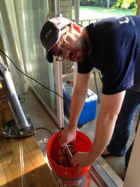
 |
| Test fitting the plywood into the bucket. Notice the cooler in the background that formerly housed the instrument. |
I bolted the infrasound unit to the wood by using "plumber's tape" or metal strap with holes down its length. This isn't the most elegant solution, but it meant no drilling the infrasound case which is semi-sealed on its own. It is also very easy to get the unit out for any maintenance. My RaspberryPi ended up having problems on the circuit board, so I've bolted a Beagle Bone Black to the board as well.
 |
| Front of the mounting board. Infrasound unit (right), Beagle Bone (left), and power plugs (top left). |
 |
| Rear of the mounting board with power passthrough. |
 |
| With no tall standoffs handy I made use of locking nuts, washers, and other assorted 4-40 hardware. |
Two holes were drilled in the side of the bucket: one for the power and one for the air tube to the infrasound instrument. I passed the power cable through (outdoor zip cord) through as well as clear plastic tubing and sealed it with bathroom silicon sealant. I'd recommend sealing on the inside and outside of the bucket bulkhead. Make sure to leave extra cable and tube for drip loops. A drip loop like structure was fashioned on the outside of the bucket to ensure no rain would blow up the tube into the unit. We taped the tube down and then ran beads of silicon to secure it to the bucket. After the sealant dried we moved the tape and secured the rest of the tubing.
 |
| Power and air tube sealed into the bucket and loops to prevent water flow. |
 |
| Inside the bucket: notice the power plug. |
In later posts we'll talk about how the power is actually provided and such, but the part that pertains to the hardware is the mounting of two binding posts on the plywood at the standard 3/4" spacing. This allows us to power the board from a banana jack on the bench for testing or operationally in the bucket. I drilled a passthrough hole to send power from the back of the jacks to the front of the panel.
Initially I built a 5V regulator to power the computer with from an LM7805 linear voltage regulator, but this was indeed a poor choice. Even with a decent heat sink, the chip still got blistering hot when I was drawing 700mA (of the 1000mA rated power). Considering this would be outside in the summer heat and the fact that I didn't want the failure point of a mechanical fan I decided to use a buck voltage converter. Linear regulators dissipate all extra power as heat. For example: I was feeding 12VDC to the converter with a 700mA load running at 5VDC. That means that (12V-5V)*0.7 = 4.9 Watts of power was being turned into waste heat! No wonder, remember we think of watts as energy/time (Joules/second actually). That's a lot of wasted electricity and really just a complication to our design, but it was very clean power.
 |
| The old linear regulator. It's now awaiting a new use in the parts bin. |
The buck converter is a switching type regulator. I don't want to get into how switching regulators work current, but it's an interesting topic and you should have a read on the theory if you like. I bought a small unit (P/N 1385) from Adafruit that is rated to 3A (though it gets warm there). The power isn't quite as clean from this switching supply, but it's fine for out use here. It works great with the Beagle Bone and provides lots of extra power for 5V accessories. Don't want to order and ship from Adafruit? You can get the exact same thing from a model shop. They are called "battery eliminator circuits" and allow modelers to plug their airplane, car, etc servo electronics (5VDC operation) into a 12V battery they already have in their kit. Just clip the 3 pin servo plug off the end and you are ready to go. Don't forget good soldering practice and to use heatshrink tube! Shorts could spark a fire, which we don't want.
 |
| The "battery eliminator circuit" or my 5V buck converter to supply 5VDC to the Beagle Bone. |
So there it is! Next time I'm going to talk about setting up the power and network infrastructure. Maybe even the serial communications! We're going to try to avoid using a serial-USB converter since the Bagle Bone has only one USB port (that I'm using for a WiFi adapter), I don't want to use a hub, and it's a chance to learn about signal level shifting and wire into that temping header on the board.
 |
| Everything fit into the bucket nicely and powers up from the bench power supply. |