Monthly Archives: December 2015

Mill Time - Back in the Shop

While home for the holidays, I decided to make a little calibration stand that I need for a tilt meter project I'm working on. Back in the 2006 time frame I had worked to learn basic machining skills on the mill and lathe. I never was amazing at it, but managed to get a basic skill set down. I ended up back over at my mentor's shop this week to make a simple part, but thought you may enjoy seeing some photos of a simple milling setup.

The first step is to have a part design that is exactly what you want to make. Problems always arise when you have a rough sketch and make it up as you go. For some hobby projects that can work, but as our systems become more and more complex, it generally just leads to wasted time, material, and lots of frustration. This particular part is exceedingly simple, but I went ahead and made a full 3D CAD model anyway, just to illustrate the process.

Our goal is to make a flat plate for a tilt meter to set on. We will then elevate one end of the plate a known amount with precision thickness pieces of metal called gauge blocks. Knowing the distance between the ends of the plate and the amount we elevate one end, we can very accurately calculate the angle. That lets me calibrate the readings from the tilt meter to real physical units of degrees or radians. All good designs start with a specification, my specification was I wanted at least 5 different tilts ranging from 0 - 0.5 degrees, the more combinations possible the better. I also wanted a compact and rigid device that wouldn't bend, warp, or otherwise become less accurate when tilted.

Time to fire up a Jupyter notebook and do some calculations! I mainly wanted to be able to play with the tradeoffs of baseline length, height of gauge block (they come in standard sizes), etc. After playing with the numbers some, I came with up a design that used multiple baseline lengths with available gauge blocks. I decided to use ball bearings under the plate to give nice point contacts with the surface of the table as well. This meant I needed a plate about 6" x 12" with hemispherical divots to retain the bearings.

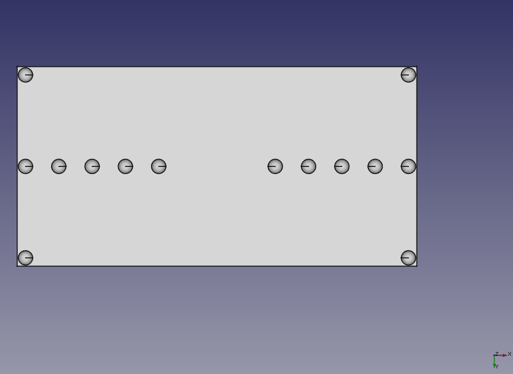
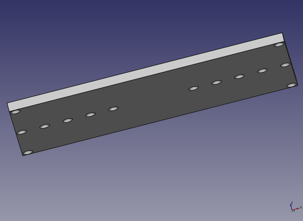
Next, I fired up FreeCAD and made the design by taking a 6" x 6" plate and using 0.5" spheres as the cutting shape to make the divots. The divots are only 1/8" deep, so setting them in 1/4" from the edges is enough. Then I just mirrored that 6" x 6" part to make the full part. This lets me tilt both directions the same amount without turning or moving the instrument under test. The drawing I produced is shown in both bottom and oblique view.

bottom oblique

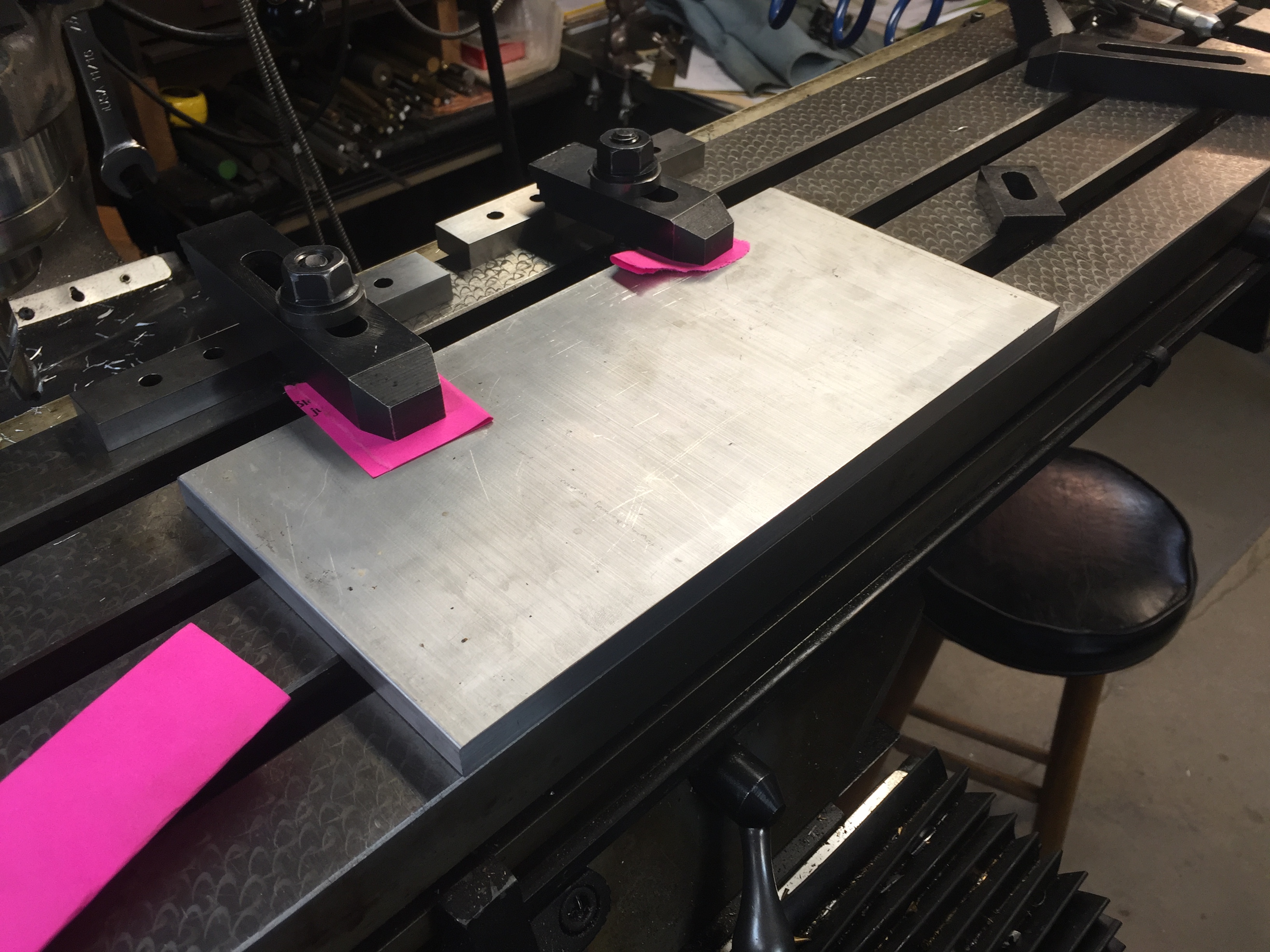
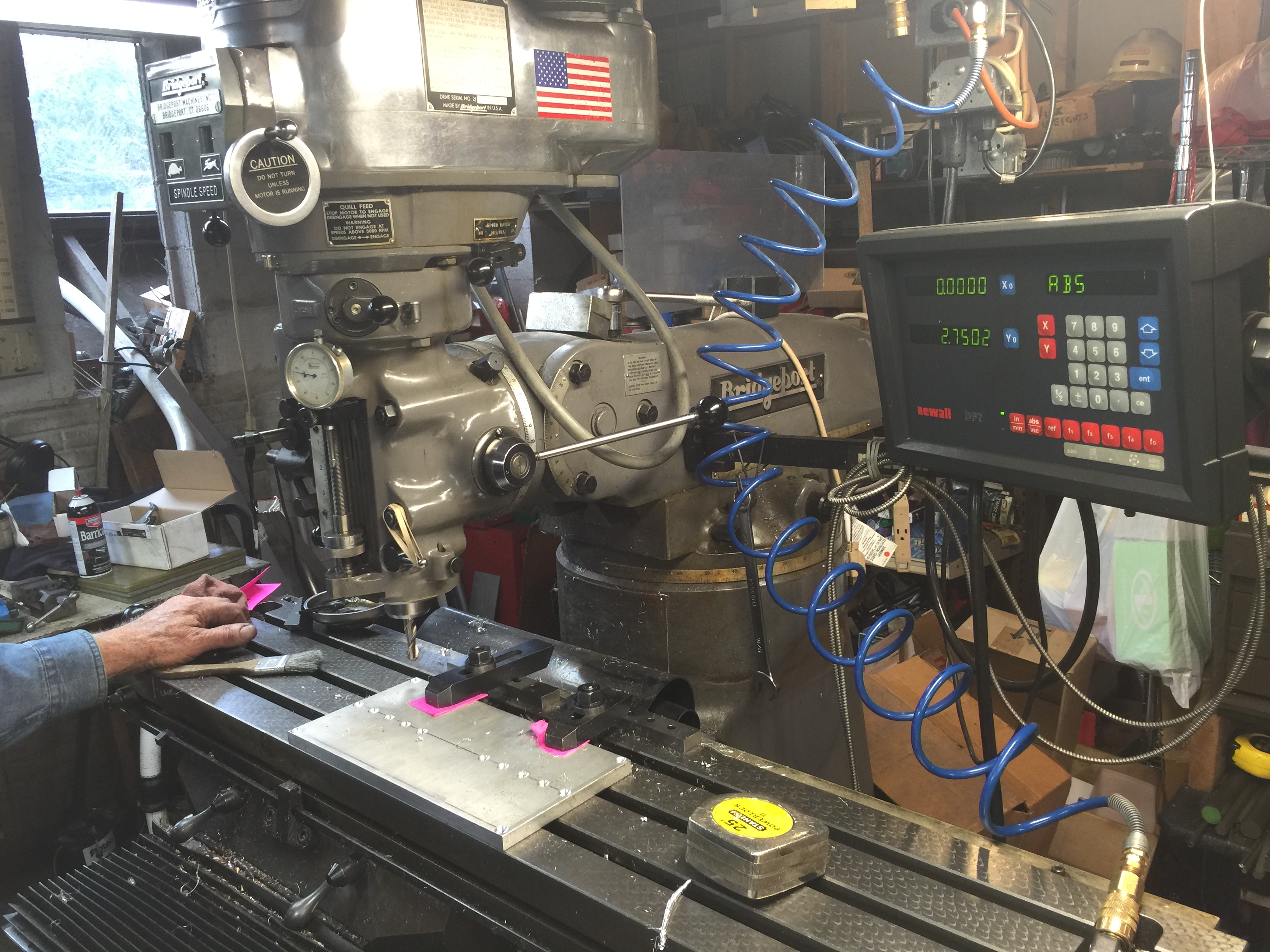
Next it was time to make the plate. I ended up with a piece of 0.5" thick 6061 Aluminum plate. We first cut it to roughly the size we wanted (slightly oversized) with a bandsaw. Then the plate was clamped down to the milling machine table to take off the extra material with a milling bit and give the sides a nice and clean finish. We ended up re-clamping during the work (almost always a bad idea) and had a slight taper on the width, but that isn't a concern for the usefulness. (By slight taper I mean about 20 thou along the length.)

We then were ready to make the divots. To do this we used a ball end mill that makes nice hemispheres. This is a very simple part, so just finding the edge, setting the readout, and doing the cuts took about 20 minutes. I've included some photos incase you haven't seen a milling setup before. It's really great fun to be able to control these cutters and tools to a thousandth of an inch and sculpt metal into what you need. As I said, this isn't a complex part, but that's good because I was a little rusty!

2015-12-30 10.15.19 2015-12-30 10.51.59

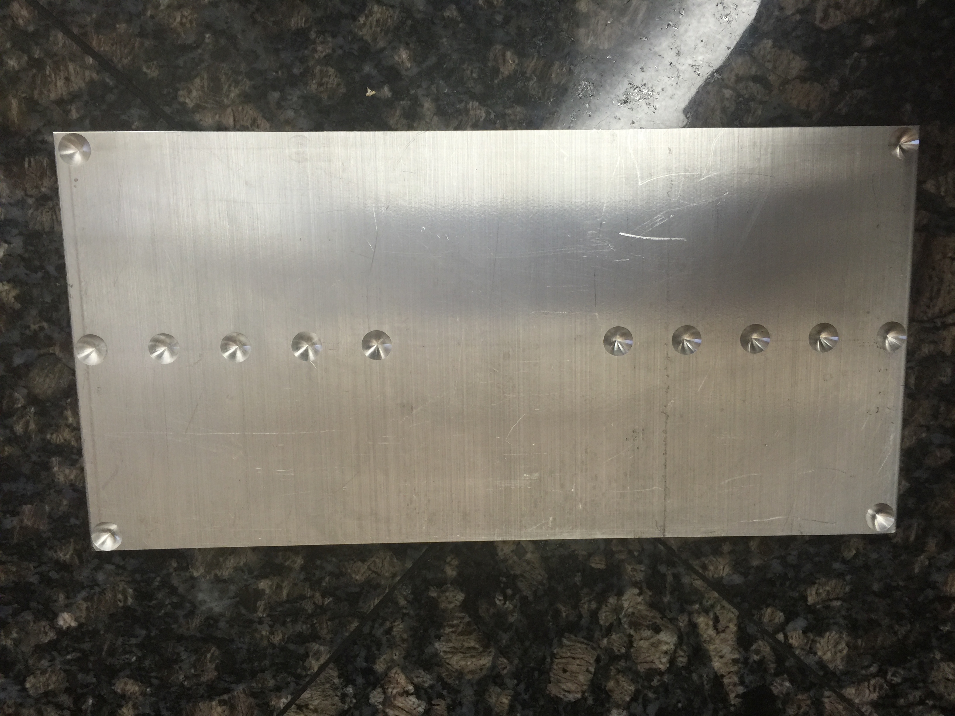
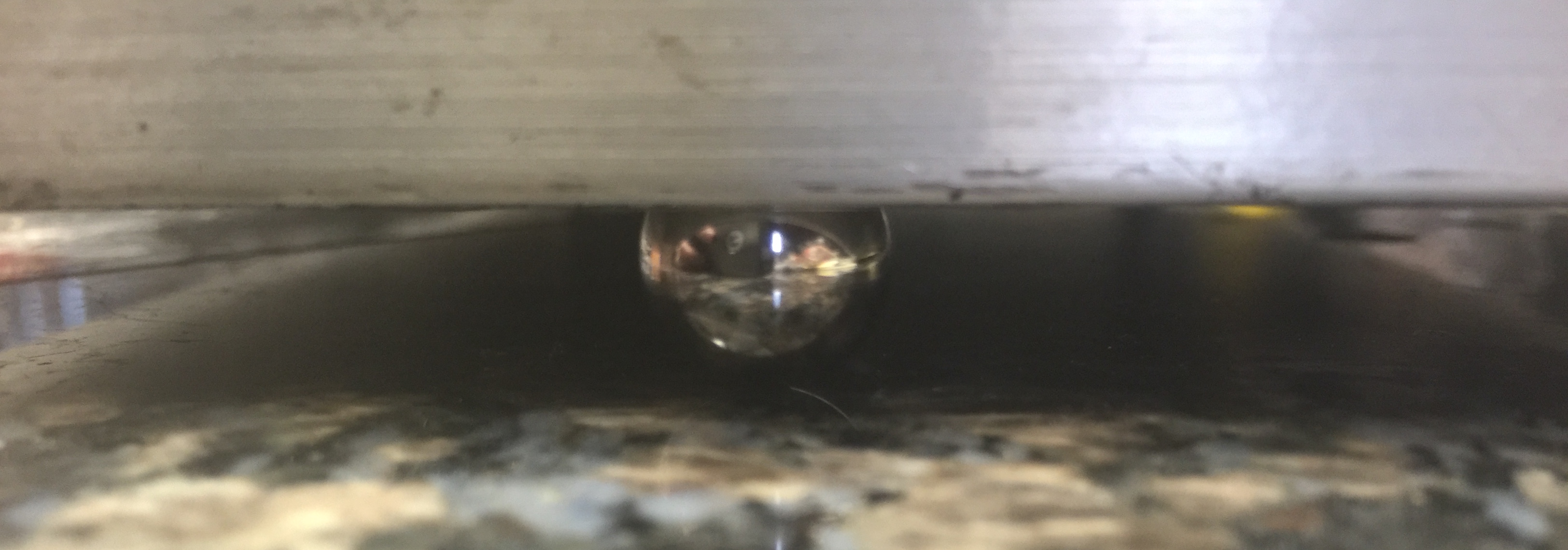
In the end we got a nice plate and I think it will perform its duty very well. I'll most likely write a future post showing it in use and explaining instrument calibration. I've included some pictures of the finished plate and how it will work sitting on the ball bearings.

2015-12-30 15.45.32

2015-12-30 15.46.50

Until next time, have a happy and safe new year!

3D Filament and Humidity - Why My Prints Keep Failing

Awhile back I talked about some weird issues with my 3D printer filament being damaged by UV radiation from the sun. I'm back with more stories of 3D printing though and my current attempt at solving the issue.

I was printing some parts and kept having issues with the layers coming apart and/or having a bubbly, uneven surface texture. I generally print with ABS plastic, even though others seem to have more issues with it, I've always had better luck than with PLA. I decided to try some PLA and also had problems with it sticking and with the filament becoming very brittle and shattering. This problem was slowly driving me crazy as I usually can get high quality prints with little fuss.

First off I moved the printer further away from the window to be sure no hot/cold convective air currents were interrupting the printing process. I even hung some cardboard sheets around the side of the print area. If I had the space I'd make a full enclosure for the printer to cut off all air currents from the room, but that will have to wait for awhile. (It would also dampen the noise, which is a bonus in an apartment!) I still was getting "bubbly" prints though.

Cardboard baffles taped onto the printer in an effort to reduce air currents near the print surface.

Cardboard baffles taped onto the printer in an effort to reduce air currents near the print surface.

After reading more online I decided that my filament must be too moist. The plastic is adsorbing moisture from the humid air and that turns to steam in the print head, causing little blow-outs and my bubbly texture. After consulting with a colleague that does a lot of printing, he confirmed that this is an issue and even cited his tests showing that filament over a few weeks old produced weaker prints. There are a few ways I can think of to help with the issue: 1) put filament in a bucket with a light bulb as a heater to keep the humidity low, 2) keep the filament in vacuum packs, 3) lock it in a low humidity environment with silica gel beads. Based on cost and convenience, I ended up going with the third option. While this technique won't give filament an infinite life, I was hoping to salvage some of mine.

I went to a craft store and bought a plastic tub that had a soft air/water tight seal; specifically the Ziploc Weathertight series container. I also ordered a gallon container of silica beads that are commonly used to keep products dry during shipping. While the products were on their way, I collected a bunch of plastic containers and drilled many small holes in them. When the beads arrived I filled the containers with them and placed them and my filament in the large box.

2015-11-01 20.30.35

In an effort to see how good of a job the silica beads were doing, I also taped a humidity indicator inside the box. I hadn't used these simple indicators before and had no idea how accurate they were, so I whipped up a quick sensor with a MicroView (Arduino) and checked it. To my surprise, it was dead on, even when exposed to the higher room humidity. If you only need 5-10% accuracy (like when seeing if the silica beads need to be baked because they are saturated) these seem to do the trick.

A close-up of the microview showing 17% RH inside my container.

A close-up of the microview showing 17% RH inside my container.

The humidity indicator also shows below 20%, matching the electronic sensor.

The humidity indicator also shows below 20%, matching the electronic sensor.

Once I verified that this solution might work, I put the rest of the filament and anything else I wanted to stay dry in the tub. Still lots of room left for future filament purchases, unpainted parts, and all of the surface mount sensors that need to be stored in a dry environment.

2015-11-01 20.30.28

After letting the filament sit in the box for a few days, I tried another print. To my surprise, there were no more blow-outs! I still have a problem with part of my print bed not adhering very well, but that's another story and another, currently only partially solved, mystery. For now, this box solution seems to have part of my 3D printing problems solved. I have noticed that old filament does produce weaker prints, so I'm going to start stocking less filament and print most things in a single color (probably just black and white unless a special need arises).