Category Archives: Education Opportunity

Fluxgate Magnetometer Wrap-Up (For now)

Per lots of emails and requests I’m going to post what I have from the design of the fluxgate magnetometer mentioned in several previous posts (like this one).  The schematic attached at the bottom is a rough draft, but should provide some guidelines for designing and building a version of this instrument.  I’ve also attached links to several PDFs that I found very helpful when building this demo.

It should be noted that this design doesn’t have a plain readout with XXXXXX nT magnetic field, but displays a waveform on the oscilloscope.  Could one be made? Absolutely! Since this was more of a demonstration of the underlying physics I didn’t bother, but it would be a good weekend project.

First off let me list a few things I would build differently were I building this again:

-       Use shielded lead wires to reduce crosstalk to the coil.

-       Use a simple Analog-to-Digital converter so this output is projected from a laptop to the classroom screen (much easier than gathering students around an oscilloscope).  I think an Arduino might do the trick.  Raspberry Pi would be a good choice too.

-       Add gain adjustment knobs to the control panel.

-       I would again use the Velleman kit for the signal generator instead of re-designing the wheel.

When using this in the classroom I laid it alongside commercial magnetometers on the table.  We discussed the physical principles behind the instrument, and then students would use the demo fluxgate to generate an output wave.  Afterwards we used the commercial magnetometers to do simple tasks like finding conduits and keys. 

It would also be nice to have a first-principles proton-precession magnetometer.  There is a book “Signals from the Subatomic World: How to Build a Proton PrecessionMagnetometer” that describes one such instrument, but significant improvements in the instrument could be made with modern programming languages and ADC devices. 

I still welcome questions on the fluxgate and will probably update the instrument next time I teach an Intro Geophysics course (undetermined).  Thank you for all the interest and if you build one, please send your results and we’ll put them up here for all to benefit.  

Fun With Office Supplies - Geometric Cohesion and Staples

After the small rash of tape theft resulting from my suggestion at a talk that the audience go home and unroll scotch tape to see the resulting electrical dischange (which deserves a blog post soon) it's time for another attempt to make Swingline Co. stock soar.

In a recent Physics Today article "Geometric Cohesion in Granular Materials", Scott Franklin of the Rochester Institute of Technology showed some very interesting data regarding how the shape of a material effects how likely it is to stay together as a coherent mass.  Before we delve into the article though, let's talk about cohesion in general.  Then we can come up with a couple of fun experiments that you can do at home.

Cohesion is just the tendency of a material to stick together.  This is different than adhesion though.  Consider a water drop on a dish in your dish drainer.  The water drop is sticking to another material (the ceramic) which is adhesion.  The water drop is also a coherent mass; water molecules are sticking together to form a raised droplet on the surface of the plate.  In essence the water is 'sticking to itself', which is due to electrostatic forces of water being a polar molecule.  Electrostatic forces give water a property of surface tension that causes lots of wonderful things that can make up a whole other post at some point.

Other things can cause a material to stick to itself though.  Remember playing the old pickup sticks game as a kid? The object was to extract a stick from a pile of sticks on the table without disturbing other sticks.  This turns out to be pretty challenging.  Your pile of sticks appeared to be stuck together or interconnected, which is cohesion in a macroscopic or broad sense.  In the case of the sticks electrostatic forces certainly aren't the cause.  Electrostatics forces are relatively weak, and the sticks don't have enough mass for their gravitational attraction to cause this cohesiveness of the pile.  What is the mysterious factor then? It's just their shape. When objects act cohesive because of their geometry or shape it's called geometric cohesion.

First grab a couple of tablespoons of sugar, place it in a small container (an old medicine bottle works great) and turn the container upside down on the table.  Now remove the container... the sugar spreads out in a small pile.  The roughly spherical grains of the sugar don't stick together that well and the pile isn't very tall.  The angle of the pile from horizontal is called the angle of repose, and is around 30-35 degrees for lots of things.  My pile of sugar sat at about 30 degrees.  The angle of repose really tells us how hard it is for the grains to slide past one another.  If it's easy, the pile is a very low angle, and if the pile is made of large, angular hunks of rock, it becomes more steep.

The angle of repose can even be thought of as a proxy for the coefficient of static friction, or how hard it is for the grains to move past each other from a dead stop.  A mathematical relationship can be derived from some geometry, but it turns out the tangent of the angle is about the coefficient of friction. So the tangent of 30 degrees is about 0.6, which is the general number for static friction of lots of materials.  This result means all is well in the world of static newtonian physics and we can think about something more interesting than approximate spheres of sugar.

What about rods? Going back to our game of pickup sticks, the shape of the long, narrow rods seems to be the main factor holding things together.  It's easy for lots of objects to interact and become 'locked together'.  Who cares about rods locking together? Manufacturers often have automated assembly machinery that may have large hoppers of screws, and when things get locked together it costs money.  The long narrow shape of screws can jam hoppers in seconds and hold up the entire line.  While not many people have a pile of tiny screws at home, I bet you have staples.

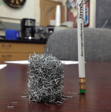
Staples are a funny shape really.  Standard office staples are about 7mm along the long upper shank and  around 5mm at the two barbs.  These measurements give the staple a barb to shank ratio of about 0.7, which as it turns out, is a governing number describing how well staples can stick together.  Franklin's group did a whole series of experiments with staples of different barb ratios and found that staples with a ratio near 0.4 were the most cohesive.  Even though our staples aren't the ideal ratio let's repeat the sugar experiment.

Using a stapler, eject a bunch of staples into the same container (or one with a slightly larger mouth if you have it).  Now shake the container up for a bit, turn it upside down, and remove the container.  This time the mass didn't spread like the sugar, but retained the relatively sharp edges of the container shape.  Retention of shape tells us that the staples are cohesive, and their high angle of repose means that the coefficient of static friction is very very high.  Franklin's group is currently seeing how strong these piles are by pulling on the ends, but they are actually pretty robust.

The big question is why does any of this matter other than being interesting? Well, cohesion is a big deal when we study soils.  Cohesion can determine if the ground can support a building, if a landslide is due, or if the machine powder coating your morning doughnuts gives you a plain doughnut.  While some of these are more life threatening that others, it's import to study cohesion to keep tabs of impending disasters, especially avalanches and landslides. I know that there aren't that many staples in soils generally, but there are clays which are shaped like plates.  Different minerals/materials in the soil with different shapes can greatly change the strength of the soil and how likely it is to slide as a mass.

3D Printing in the Lab - Will Lab Hardware Follow Software into Open-Source?

Today I read the article "Building Research Equipment with Free, Open-Source Hardware" by Joshua Pearce from a recent Science Perspectives section.  I'd like to share some thoughts on the article as I thought it introduced what may be the next "want" item in many labs.

In the modern scientific lab there is a large assortment of sophisticated hardware necessary to conduct increasingly complex research.  Generally scientific hardware is some combination of turn-key or off the shelf equipment and equipment designed and built in house.  In recent years laboratory software has progressively become part of the free and open-source software (FOSS) movement; hardware is now following the same trend with the advent of open-source 3D printers from the hobbyist community.

Open-source hardware became popular in the late 90’s with the basic stamp “board of education” microcontroller circuit boards, but the Arduino has taken over the hobby market with its $30 price tag.  Arduino has a number of modules, or shields as they are called, ready built with significant code libraries available.  With the Arduino circuit boards scientists can perform basic hardware control with digital and analog outputs in addition to basic analog-to-digital conversion.  

The RepRap open-source 3D printer is driven by the Arduino and can be constructed for <$1000.  The machine prints the parts required to make another RepRap printer, so building a machine is approached by entering the RepRap community with a parts request.  Users also post 3D designs on Thingiverse for download and printing by anyone.  A sufficient amount of laboratory equipment from test tube racks and filter wheels to Dremel tool adapters are already online.  

Printing laboratory equipment may not only reduce the cost of research, but allow the same flexibility, innovation, and rapid development cycle enjoyed by scientific software.  Being able to create a custom bracket, holder, mold, or sample jig could be advantageous to almost any laboratory and allow research to be conducted more efficiently with less focus on coordinating development with engineers at commercial manufacturers.  The open-source nature of the parts library will reduce duplication of work between those in a common field of research and allow cross-lab standardization of sample preparation techniques.  

There are limitations to what can be easily constructed in the lab, such as 3D printing with metal.  The technology to do this exists, but is too complex and expensive at the present time for individual applications.  While working at Oak Ridge National Laboratory I got the opportunity to see 3D printing with titanium.  The video below is a titanium ball... bouncing. (Apologies for the portrait video and quality, this was taken several years ago with an early iPhone.)


Like all community projects, the RepRap is being updated to have greater capabilities.  According to the project website a major milestone will be printing with electrical conductors to manufacture rapid prototype circuit boards without milling away copper clad board material.  

Just as sometimes labs must use commercial software, it is likewise not expected that all lab hardware will become open source.  Some tolerances are too tight for the parts to be constructed by simple printers and some materials are not practical to print in the lab.  With all this in mind it is worthwhile to monitor the progress of open-source hardware such as the RepRap, Arduino, and the new RaspberryPi single board computer.  These tools may provide teaching support also as controlling and displaying data from classroom demonstrations is easier than ever and does not require the resolution/precision of research grade instruments.

Building a Fluxgate Magnetometer Part 2

With school starting progress has slowed some, but currently most of the system is constructed.  First off the sense coil had to be finished.  The wire ends were coated in fingernail polish to keep the coil from slowly working undone and the entire setup was placed into a clear acrylic tube to protect it from wear.  The tube was stopped with standard rubber plugs and a computer power cord was soldered on for connection purposes.

With the function generator working it was time to amplify its ~100mV output to something that would induce a larger field via the driver coil.  Finally I decided to go with an operational amplifier (op-amp) design.  This requires both a positive and negative voltage source which is easily accomplished with two 9V batteries.  The signal generator will be run off a third battery because it is crucial that the two op-amp supply batteries remain at equal voltages.  My initial breadboard design (below) clipped the waveform badly (also below).  After some readjustments and gain fiddling a nice waveform was reached.  I built two amplifiers on a perf-board (one to amplify the signal to the driver coil and one to amplify the signal coming back from the sense coil).

It was also time to being thinking about a case/display.  Lexan seemed like the obvious choice so students can see inside.  I bought 2 sheets of lexan and nylon hardware to separate them.  Leaving the sides open allows easy oscilloscope probe access for recalibrating the amplifiers (I left little copper connections on the board for this purpose).  I designed the front control panel (not implemented yet) and drilled all the holes required.  Finally after mounting all the boards down to the lexan I powered up the amplifiers and they worked great (below)!

Next the bandpass filter needs to be nailed down.  I've worked on it some, but cannot get a satisfactory result to build up onto the last perf-board.  The signal that carries the information we are interested in is the 2nd harmonic of the 1kHz driver signal.  It will be weak so it is likely that the amplifier will need a bit of reworking and hopefully I can build some gain into the bandpass design (also op-amp).  The classic catch is increasing the Q of the filter, but killing the amplitude of the signal.  More to come...

Building a Fluxgate Magnetometer - Part 1 (and NASA)

Today I want to discuss the first steps in building a simple fluxgate magnetometer for a classroom demonstrator.  Originally this post was going to be a wrap up of NASA work and the magnetometer would come later, but I'm still waiting on my presentation to clear export control so I can post it.  As soon as it does, I'll put it up along with a short article.

This semester I'll be the TA for 'Global Geophysics', mostly doing lab instruction/writing.  After some thought I decided that students need more hands-on classroom geophysics, which is difficult to do.  By its nature geophysics is an outdoor activity with normally expensive instruments.  The instruments are often viewed as a mysterious black box that spits out numbers used to make a map.  This must change.  With a proper understanding of the instruments students will better understand errors in the data, how to troubleshoot in the field, and know why certain hardware limits exist.

The concept of a fluxgate magnetometer is pretty simple.  Rather than go into detail I'll refer you to this wikipedia article.  This is mainly to chronicle the construction so others can reproduce this (assuming we get a working model).  My design came from a physics lab at Brown University.  The instructions were vague in parts and I'll be taking some liberties as we go along.  This first article will cover construction of the coil and the driver circuit.

The fluxgate coil consists of a driver coil surrounding a soft steel wire, and a secondary coil to pickup signal surrounding the primary coil.  First I took 16ga annealed steel wire from Lowes and cut it to about 1m long, cleaned it, and made it as straight as possible.  Afterwards I wrapped close to 2000 turns of 22ga magnet wire (Radio Shack #278-1345) tightly along its length.  This was then bent in half making a 'U' and that was wrapped with close to 1000 turns of 26ga magnet wire. I used large wire because it will be more durable and I used different gauge wire since the enamel insulation was a different color allowing students to easily see the windings.

That's all there is to the coil.  To increase durability I will probably clear coat the coil and place it into a small acrylic tube so its difficult to bend or break.  The next step is to build a driver for the primary coil.  The Brown lab used a function generator.  Currently I don't have one, nor have I found a suitable cheap unit.  This meant improvising, and luckily Velleman makes a signal generator kit that is just about right.  It operates at 1kHz (the desired frequency for this project) and produces sine, square, triangle, and integrator waves.  The kit was pretty easy to build in just about an hour and works well as seen by the oscilloscope output below, but frequency stability is not phenomenal (especially when then unit is cold).  

Next a few amplifiers need to be designed and built.  The signal generator kit cannot pull the load of the coil, so a simple +/- 9V system will probably do.  The output will also need some kind of amplification.  The lab I found also uses a bandpass filter.  Once the amplifiers are working it will be time to decide if this is necessary and if I want to use an oscilloscope and hardware filters, or an ADC and display the waveform on a computer projector using software filters.  

Field Camp - The Final Week

The final week of field camp consisted of a swap between geology/geophysics students, preparation of final reports, and a final presentation.

For the first day (Monday) of the geology/geophysics swap I was helping the geologists with my homebrew resistivity rig.  After some small problems in the morning the device cooperated, and we took a like across a fault, seeing massive jumps in conductivity over the gouge area.  The second day I was actually out with the geology professors hand mapping some of the surface geology in the area.  Tom and Neil were very instructive and were able to measure a strike and dip on things that very few would term 'outcrop'.  Nonetheless the data plotted nicely!

After the mapping came independent projects and final reports.  Cullen and I decided to collect a gravity line across the dry union fault near Salida (the area of the first field trip).  I ended up staying at camp to help the geologists process their data and Cullen went with Guang to collect the line.  The results were stunning and the calculated fault dip angle is 87 degrees.

Processing the magnetic data was quite a challenge.  To take the data we place flags along the path we walk, take their coordinates and press mark at each flag.  The instrument is collecting a magnetic reading every 1/10 of a second.  I ended up writing code that assumes a constant walking place between flags and linearly interpolates positions between.  The code then re-writes a new datafile that can be plotted by OASIS.  The quick code hack was not perfect and really should have already been in the software that came with the instrument.  Hopefully over the summer I'll have time to perfect the code and write a nice GUI to go along with it.  (Error checking would also be nice)

Finally on the last day of camp we had to give a presentation of the results.  Cullen and I talked for about 40 minutes and then there was much discussion between the faculty of our image.  We had everybody excited about what we should try next year!  Unless plans change it is likely that Cullen and I will TA next year.

Now I'm at NASA in Houston, TX.  Towards the end of this week I'll start a weekly post about the work here.  It's very exciting work with a flying vehicle and guidance software.  Stay Tuned!  Below are a few pictures from the group trip to Pike's Peak.  A copy of the final report can also be downloaded HERE.

Week 2 (Seismic Week) - Field Camp 4

This week was seismic week for us here in Canon City.  We carefully selected a site that crosses from sediment into basement, but the nature of the contact is unknown.  It ran across the property of a nice couple who moved here from Iowa three years ago.  They are interested in the geology and were more than happy to have us tramp all over with magnetic, gravity, and finally seismic gear including a larger thumper mounted on an ATV.

The first part of the week involved Cullen and I working on a mounting system to attach the thumper for the four-wheeler.  Seismic surveying works on the premise that different rocks have different wave velocities as a function of the type of rock, fluid content, etc.  We set out a long line of geophones (basically a vertical seismometer) and then hit the ground very hard to induce a signal.  From the return of the signal we can learn a lot about what the subsurface looks like.

For some surveys we hit the ground with a sledgehammer, shoot it with a gun, or even use dynamite! In this case we tried a new device that pulls a 40kg weight up with an electric motor and then drops it.  There is also a giant rubberband that accelerates the weight towards the ground.  There is currently a battle going on between naming the machine the seismic thumper device or the seismic thumper and utility device.  We added weights, battery mounts, and even a flashing safety light to the four-wheeler.

Before we could even use the thumper the control box failed due to a cable issue, so I had to rewire the control system (actually just a solenoid control) and mount the switch in a box on the ATV.  It was a midnight patch up, but it worked well all day!

The survey was laid out on Wednesday.  The line was almost 750m long, then we even rolled it forward! Geophones were placed every 10m and the thumper was shot at each geophone three times to 'stack' the data (this helps us reduce random noise).  We don't have any images yet, but tomorrow we begin processing.  The line took a day to layout, a day to shoot, and tomorrow morning to roll up.  Several long days for us here.  I also put together a quick video of the thumper shooting.

On a side note, we also took a great hike and field trip in the past week, so I've added a few photos of the Collegiate Peaks, and Tunnel Drive Trail.

Week 1 - Field Camp 3

Week 1 has been very busy and week 2 is almost to begin.  We were lucky with the weather, but this week looks to begin the inevitable warm up that we all knew would come.  This week the geophysics group went on a field trip to get the regional setting (Monday), learned detailed surveying with the TOPCON differential GPS (Tuesday), conducted a gravity survey, and a magnetic survey (days dependent on group assignment).  The week ended on Saturday with another field trip out west to see some different formations.

The regional field trip went well and we scrambled across some slopes to see most of the section that the geologists would be mapping and be very familiar with.  As a geophysics student I was more interested in the rock properties, what methods we could differentiate them with, etc.  This trip did help put things in a big picture geologic perspective though.

The differential GPS surveying went well despite a few equipment setup issues, which were to be expected with new users.  The basic premise of the system is to leave a very precise GPS unit in place all day while another identical unit is used as a rover.  The two data sets can then be merged using the base to correct for signal attenuation by the continually changing atmosphere and other error sources.  In general sub-centimeter accuracy is achievable.  This accuracy in elevation is especially important in gravity data processing since 1m makes .3086 mGal difference in the data.  While some complain that taking 2 minutes to get a GPS fix is unreasonable I remind you that we are getting a very accurate position on an irregularly shaped rotating planet FROM SPACE... it's amazing it dosen't take longer.

The gravity survey looks at density differences in the subsurface while the magnetic survey examines differences in magnetic susceptibility.  We are interested in contracts between sediments and basement or with a dike especially in this area.  After the processing I will post some results, but I know the magnetometer went crazy when I passed over the suspected location of a large dike.  The gravity survey should also be helpful, but the gravimeter does instill a certain amount of fear in everyone since it is ~$100,000 and VERY easy to break.  Omar is modeling the magnetometer in this picture.

Finally, we went on another trip Saturday which involved me getting some nice rocks with chlorite in them for bookends from a tailings type pile in a field.  This week will be seismic week, so stay tuned for updates and pictures of our new (hopefully) 700m long seismic line!

Setting Up Equipment - Field Camp 2

The past few days have been working to get a solid radio link to downtown.  The internet signal comes up on a 5.8GHz link, is distributed over a 5.12GHz mesh around the camp, and is repeated to others on a 3GHz haul over the canyon.  Below is a picture of the stack at the top of the camp on the study hall.  The repeaters are mounted on the sides of cabins.  The current link is slow, but a new circuit will be installed downtown giving us a fast connection this week.  Also included is a picture of the geophysics server (named thor) and the associated gear.

We also worked on setting up the thumper.  This is a machine that attaches to a trailer hitch of any vehicle (truck, ATV, etc) and impacts the ground with a great force.  We use this in seismic imaging.  Normally we use a sledgehammer for small surveys, but that can get tiring.  For large, deep surveys explosives are used, this machine is a great middle ground.

As you can see there is still some work to be done.  Tomorrow the hitch will be modified and in the evening I'll be building some custom brackets and mounts for the controls and battery with Dr. Keranen.  We'll use aluminium angle iron to build most of the mounts, pictures will follow.

Tomorrow we all leave early for a regional trip to get the general geological/tectonic setting of the area.  This trip will be both geologists and geophysicists.

Setting Up Camp - Field Camp 1

This is the first in a series of posts I'll be writing about my experience at the new Bartell field camp. This camp will serve as the base for summer geology/geophysics students. Geologists will be here 5 weeks, geophysicists 3 weeks. I arrived early to setup computer equipment and help get things going around the place.


I arrived Wednesday and unloaded the server, 10 laptops, associated wiring/network components, and my field gear. More on the setup in the next post when we have internet and the rest of the network up and running.

The first night here the freshman field trip was also at camp, spending the night before departing to Dalhart, TX. We all hooked up the projector, hung a sheet, and had a movie night in the dining hall (complete with popcorn). The movie was 2012, one of the better geological comedies if you ask anybody there.

The camp site is beautiful and my cabin is at the top, affording the best view. This view comes at the price of walking a VERY steep trail, and at 6,200 ft. it's easy to get a bit winded. After a couple days it is not a problem though.


So far the weather has been very cool and rainy in town, but fairly dry up at camp. It's hit freezing at night making a sleeping bag necessary in the cabins. The peaks off in the distance are still snow covered, but today were obscured by rain shafts.


Stay tuned for a tech update tomorrow and then the arrival of the rest of the crew on Sunday. The next few weeks should brings lots of interesting field work and interesting results.

- Posted using BlogPress from my iPad

Location:Silverado Ct,Cañon City,United States