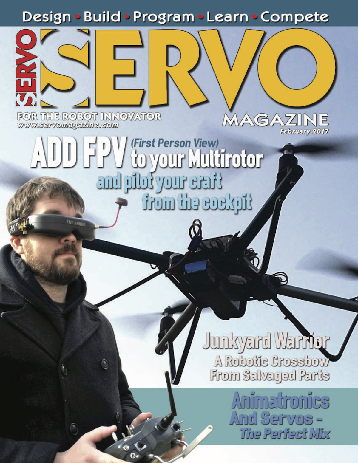
This month I was lucky enough to have a cover feature on adding a camera and googles/screen to your drone setup. Adding this "First Person View" (FPV) capability really makes flying a lot different as its like you are setting in the cockpit!
Several years ago, I rode in the copilot’s seat of a small Cessna circling over northwest Arkansas. The view was great and the experience of sitting right behind the propeller with a view of where we were headed was fantastic. It made riding in economy of commercial airliners seem even more boring and cramped than it already did. As multirotor pilots, we can now have that experience with first person view (FPV) equipment that literally puts us in the pilot’s seat and immerses us in the experience of flying.
Be sure to checkout the column and let me know of other topics you'd be interested in seeing in future articles! Right now I've got a photogrammetry series coming up after a quick CX-10 hack.
As frequent readers of the blog or listeners of the podcast will know, I really like doing outreach activities. It's one thing to do meaningful science, but another entirely to be able to share that science with the people that paid for it (taxpayers generally) and show them why what we do matters. Outreach is also a great way to get young people interested in STEAM (Science, Technology, Engineering, Art, Math). When anyone you are talking to, adult or child, gets a concept that they never understood before, the lightbulb going on is obvious and very rewarding.
Our lab group recently participated in two outreach events. I've shared about the demonstrations we commonly use before when talking about a local science fair. There are a few that probably deserve their own videos or posts, but I wanted to share one in particular that I improved upon greatly this year: Squeezing Rocks.
Awhile back I shared a video that explained how rocks are like springs. The normal demonstration we used was a granite block with strain gauges on it and a strip chart recorder... yes... with paper and pen. I thought showing lab visitors such an old piece of technology was a bit ironic after they had just heard about our lab being one of the most advanced in the world. Indeed when I started the paper feed, a few parents would chuckle at recognizing the equipment from decades ago. For the video I made an on-screen chart recorder with an Arduino. That was better, but I felt there had to be a better way yet. Young children didn't really understand graphs or time series yet. Other than making the line wiggle, they didn't really get the idea that it represented the rock deforming as they stepped on it or squeezed it.
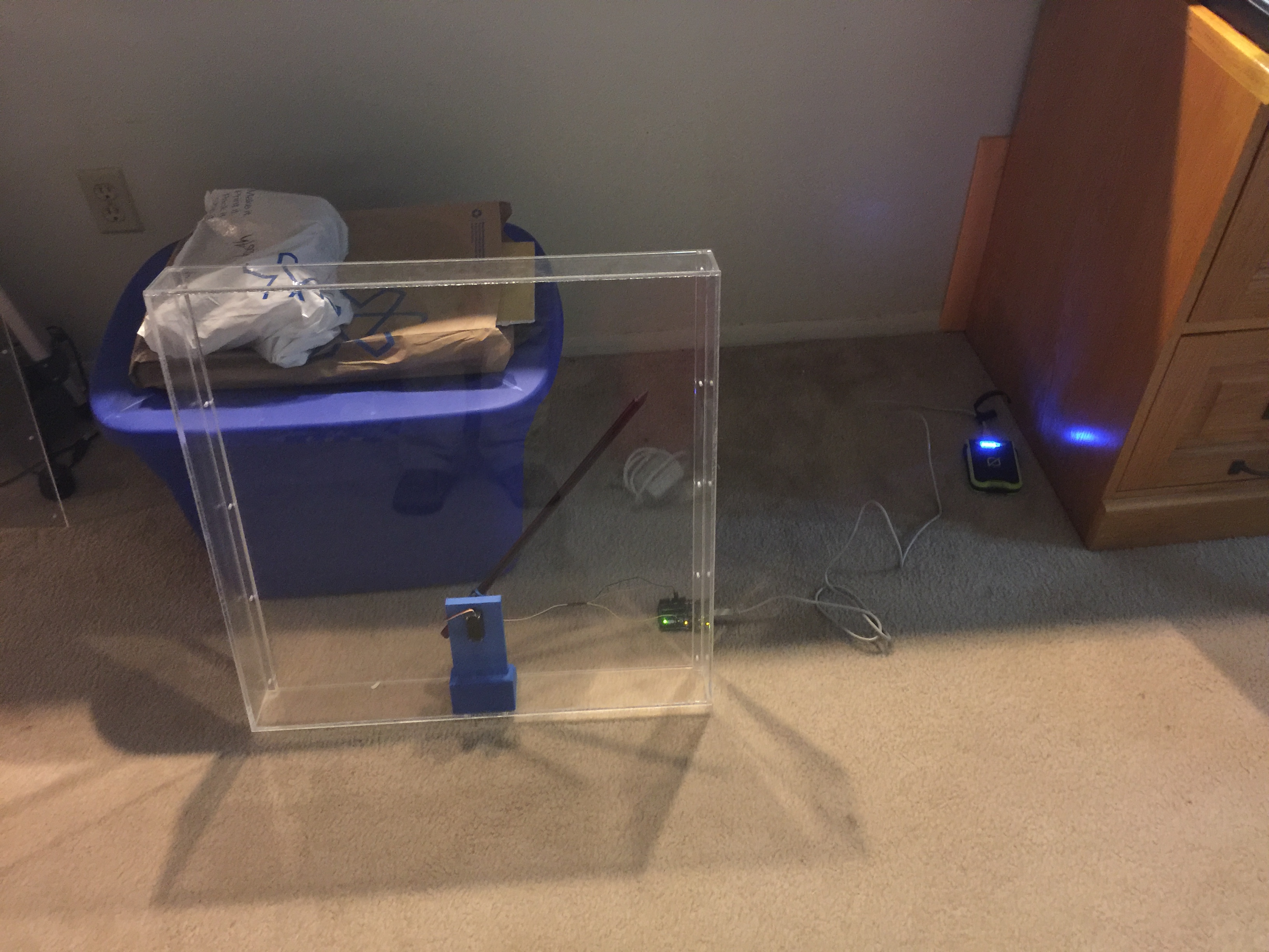
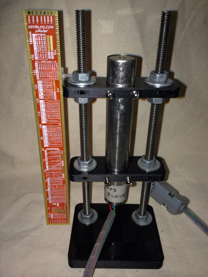
I decided to go semi old-school with a giant analog meter to show how much the rock was deformed. I wanted to avoid a lot of analog electronics as they always get finicky to setup, so I elected to go with the solution on a chip route with a micro-controller and the HX711 load cell amplifier/digitizer. For the giant meter, I didn't think building an actual meter movement was very practical, but a servo and plexiglass setup should work.
A very early test of the meters shows it's 3D printed servo holder inside and the electronics trailing behind.
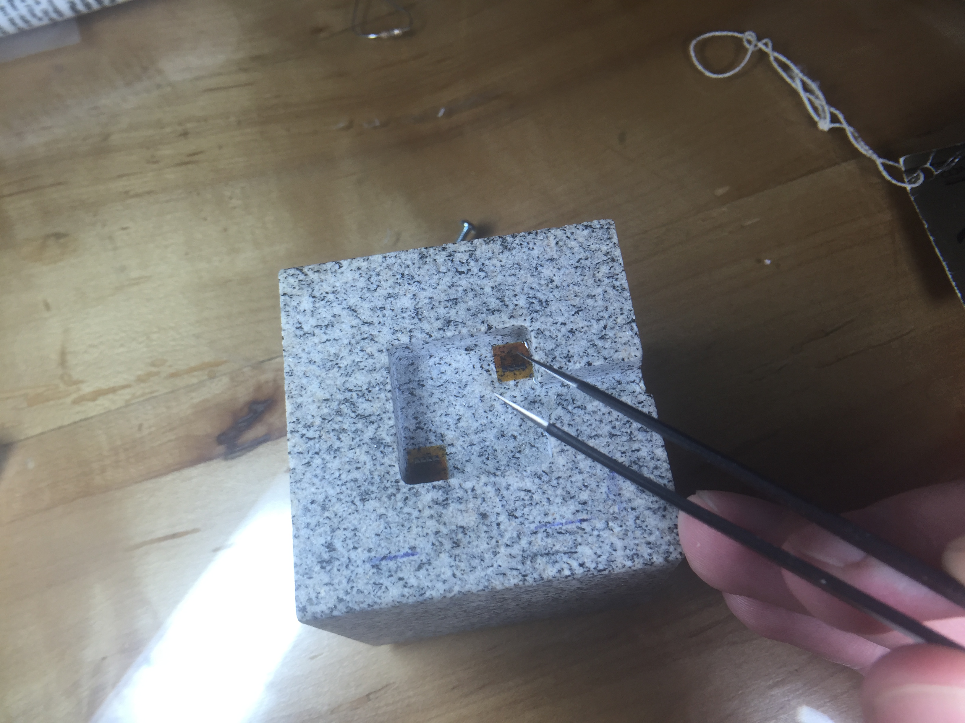
Another thing I wanted to change was the rock we use for the demo. The large granite bar you stepped on was bulky and hard to transport. I also though squeezing with your hands would add to the effect. We had a small cube of granite about 2" on a side cut with a water jet, then ground smooth. The machine shop milled out a 1/4" deep recess where I could epoxy the strain gauges.
Placing strain gauges under a magnifier with tweezers and epoxy.
Going into step-by-step build instructions is something I'm working on over at the project's Hack-a-Day page. I'm also getting the code and drawings together in a GitHub repository (slowly since it is job application time). Currently the instructions are lacking somewhat, but stay tuned. Checkout the video of the final product working below:
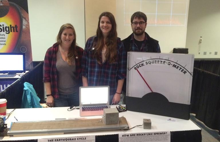
The demo was a great success. We debuted it at the AGU Exploration Station event. Penn State even wrote up a nice little article about our group. Parents and kids were amazed that they could deform the rock, and even more amazed when I told them that full scale on the meter was about 0.5µm of deformation. In other words they had compressed the rock about 1/40 the width of a single human hair.
A few lessons came out of this. Shipping an acrylic box is a bad idea. The meter was cracked on the side in return shipping. The damage is reparable, but I'm going to build a smaller (~12-18") unit with a wood frame and back and acrylic for the front panel. I also had a problem with parts breaking off the PCB in shipment. I wanted the electronics exposed for people to see, but maybe a clear case is best instead of open. I may try open one more time with a better case on it for transport. The final lesson was just how hard on equipment young kids can be. We had some enthusiastic rock squeezers, and by the end of the day the insulation on the wires to the rock was starting to crack. I'm still not sure what the best way to deal with this is, but I'm going to try a jacketed cable for starters.
Keep an eye on the project page for updates and if any big changes are made, you'll see them here on the blog as well. I'm still thinking of ways to improve this demo and a few others, but this was a giant step forward. Kids seeing a big "Rock Squeeze O Meter" was a real attention getter.
Hmm... As I'm writing this I'm thinking about a giant LED bar graph. It's easy to transport and kind of like those test your strength games at the fair... I think I better go parts shopping.
I was printing some parts and kept having issues with the layers coming apart and/or having a bubbly, uneven surface texture. I generally print with ABS plastic, even though others seem to have more issues with it, I've always had better luck than with PLA. I decided to try some PLA and also had problems with it sticking and with the filament becoming very brittle and shattering. This problem was slowly driving me crazy as I usually can get high quality prints with little fuss.
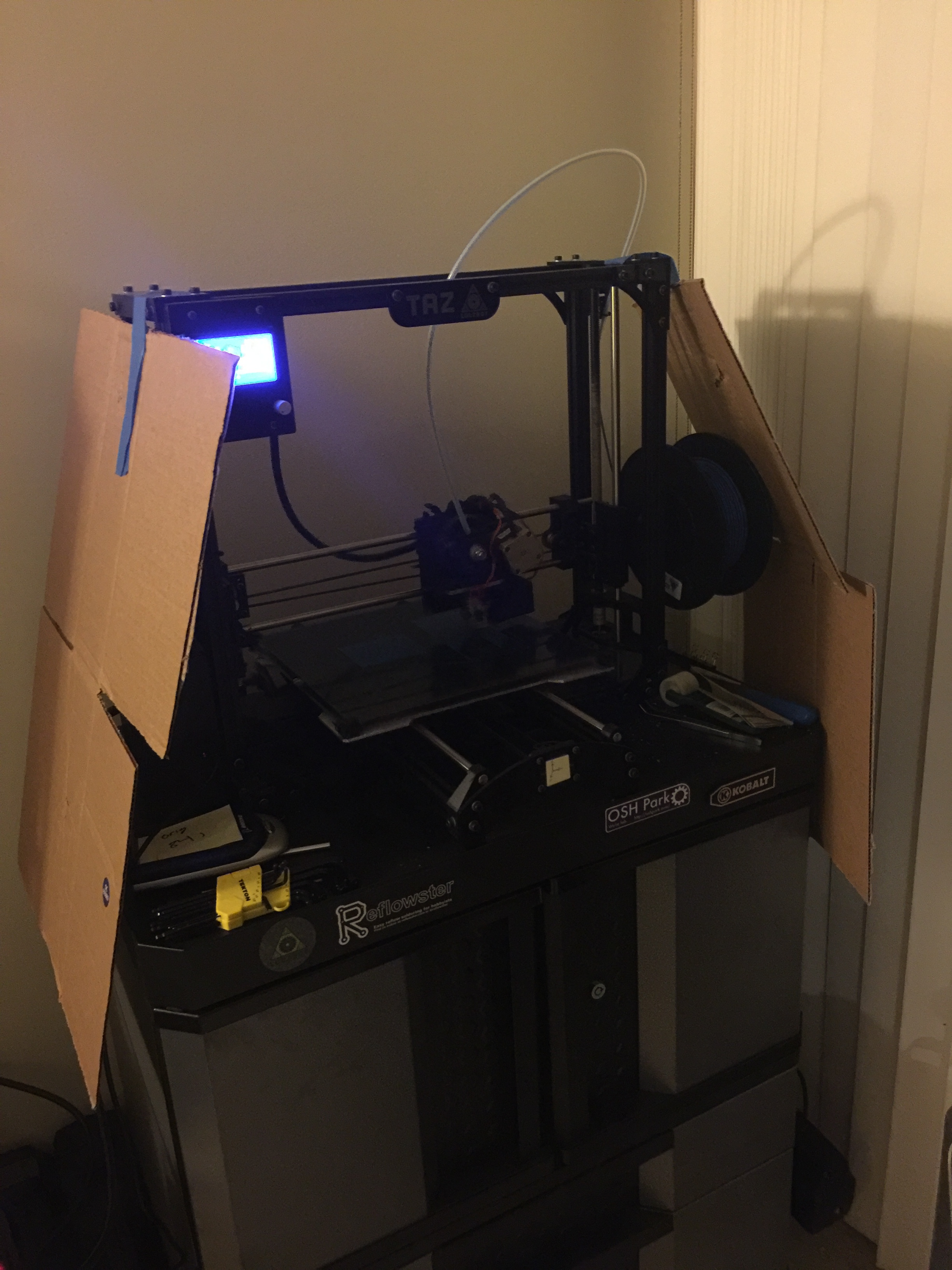
First off I moved the printer further away from the window to be sure no hot/cold convective air currents were interrupting the printing process. I even hung some cardboard sheets around the side of the print area. If I had the space I'd make a full enclosure for the printer to cut off all air currents from the room, but that will have to wait for awhile. (It would also dampen the noise, which is a bonus in an apartment!) I still was getting "bubbly" prints though.
Cardboard baffles taped onto the printer in an effort to reduce air currents near the print surface.
After reading more online I decided that my filament must be too moist. The plastic is adsorbing moisture from the humid air and that turns to steam in the print head, causing little blow-outs and my bubbly texture. After consulting with a colleague that does a lot of printing, he confirmed that this is an issue and even cited his tests showing that filament over a few weeks old produced weaker prints. There are a few ways I can think of to help with the issue: 1) put filament in a bucket with a light bulb as a heater to keep the humidity low, 2) keep the filament in vacuum packs, 3) lock it in a low humidity environment with silica gel beads. Based on cost and convenience, I ended up going with the third option. While this technique won't give filament an infinite life, I was hoping to salvage some of mine.
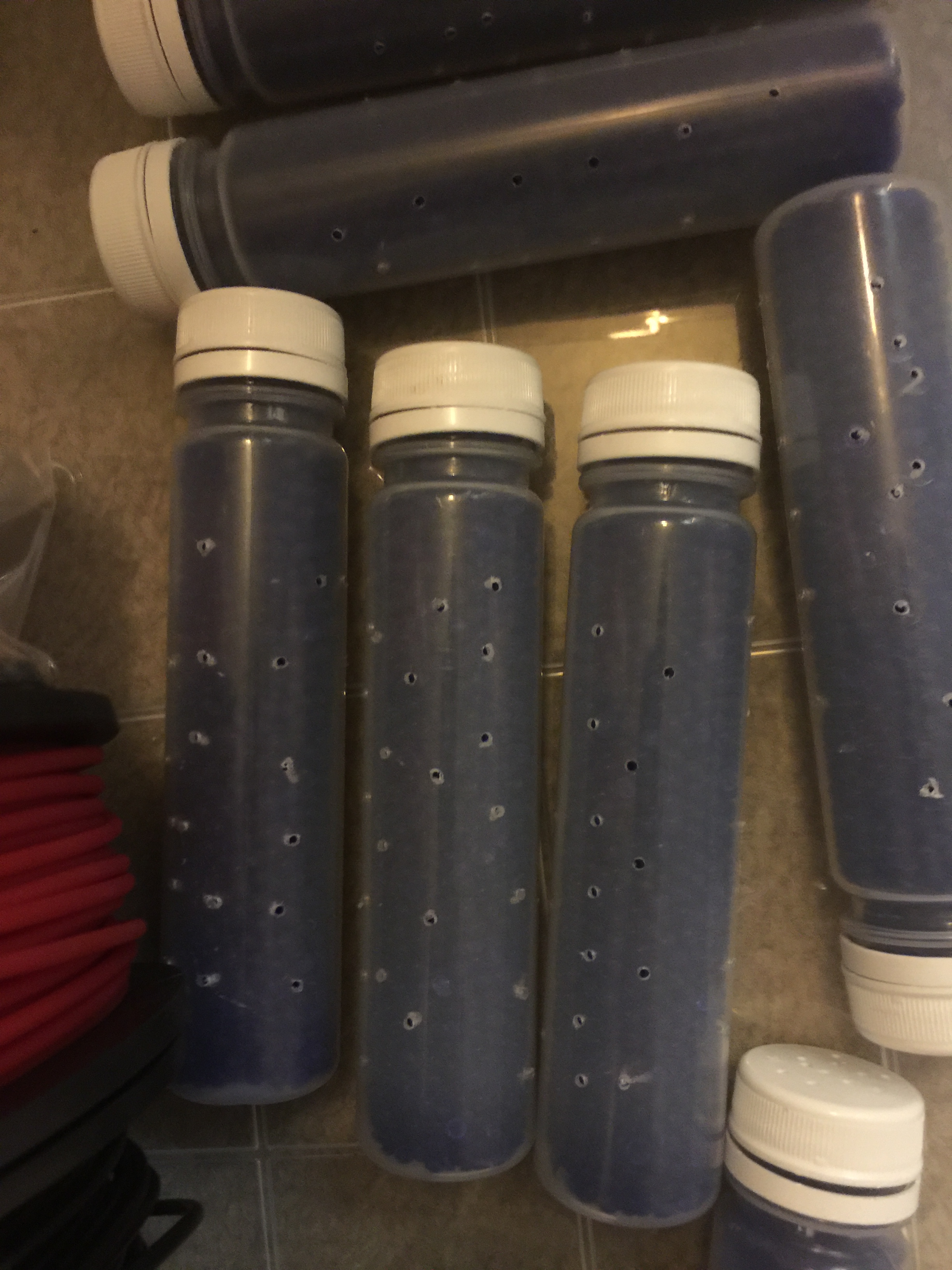
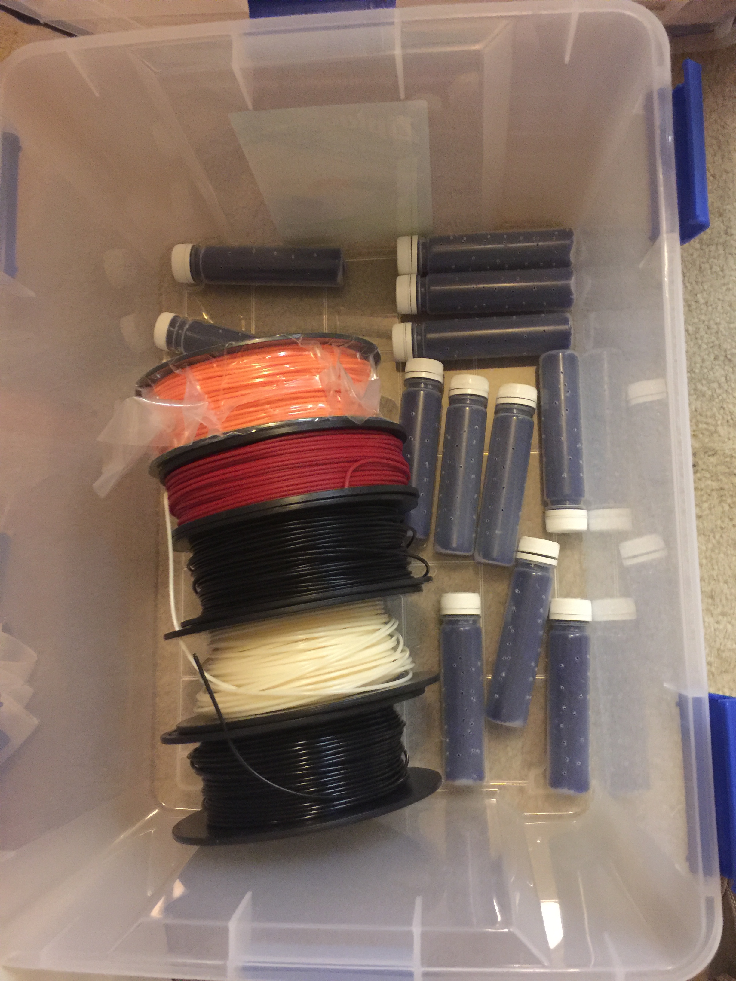
I went to a craft store and bought a plastic tub that had a soft air/water tight seal; specifically the Ziploc Weathertight series container. I also ordered a gallon container of silica beads that are commonly used to keep products dry during shipping. While the products were on their way, I collected a bunch of plastic containers and drilled many small holes in them. When the beads arrived I filled the containers with them and placed them and my filament in the large box.
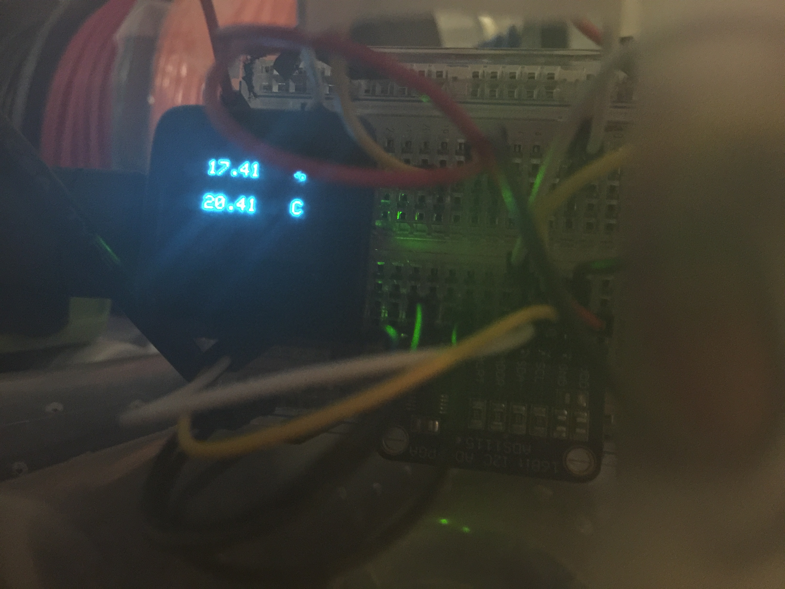
In an effort to see how good of a job the silica beads were doing, I also taped a humidity indicator inside the box. I hadn't used these simple indicators before and had no idea how accurate they were, so I whipped up a quick sensor with a MicroView (Arduino) and checked it. To my surprise, it was dead on, even when exposed to the higher room humidity. If you only need 5-10% accuracy (like when seeing if the silica beads need to be baked because they are saturated) these seem to do the trick.
A close-up of the microview showing 17% RH inside my container.
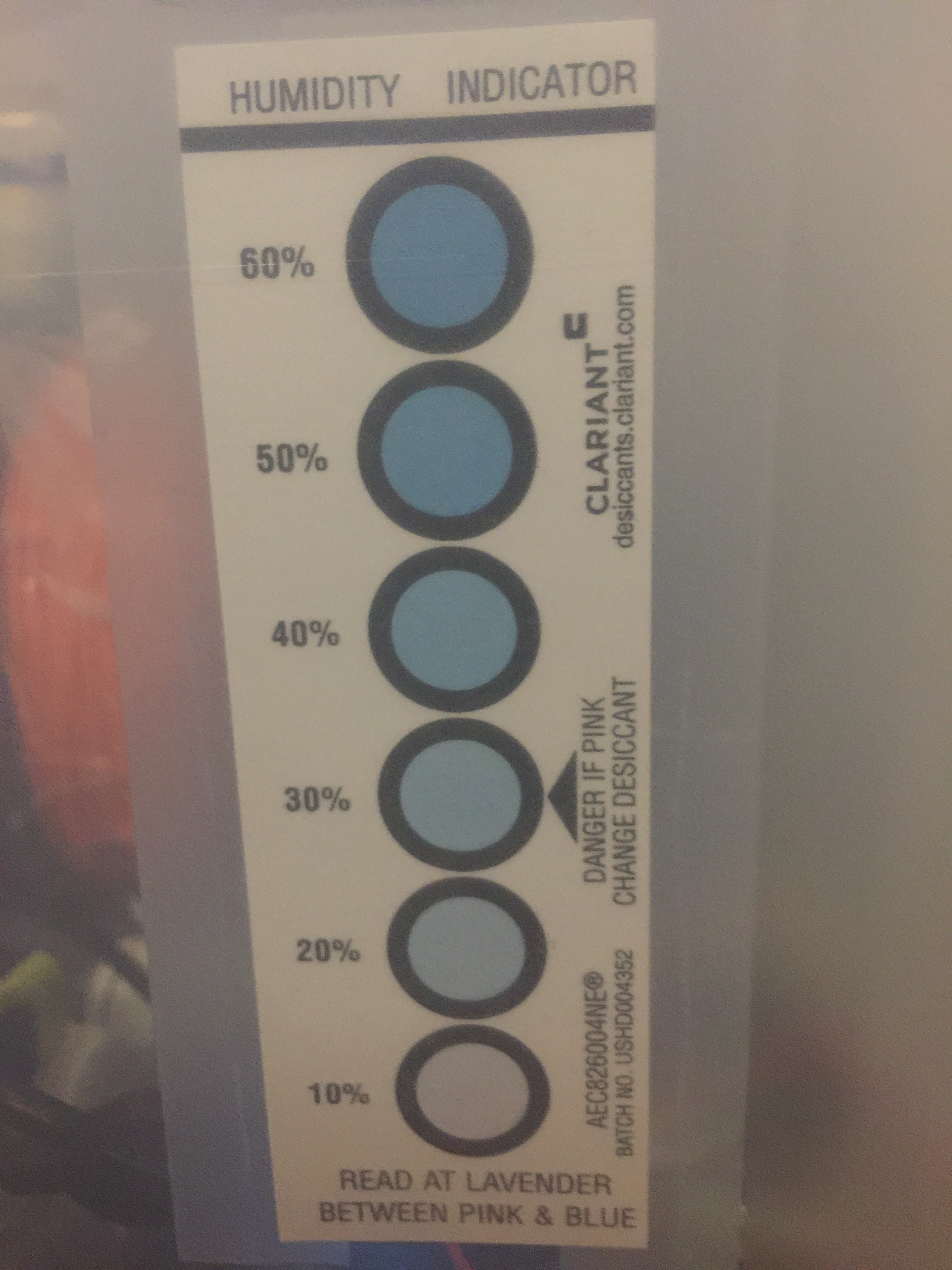
The humidity indicator also shows below 20%, matching the electronic sensor.
Once I verified that this solution might work, I put the rest of the filament and anything else I wanted to stay dry in the tub. Still lots of room left for future filament purchases, unpainted parts, and all of the surface mount sensors that need to be stored in a dry environment.
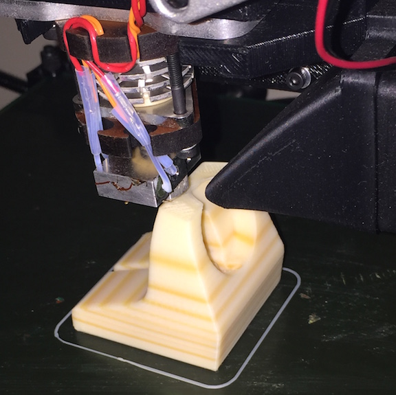
After letting the filament sit in the box for a few days, I tried another print. To my surprise, there were no more blow-outs! I still have a problem with part of my print bed not adhering very well, but that's another story and another, currently only partially solved, mystery. For now, this box solution seems to have part of my 3D printing problems solved. I have noticed that old filament does produce weaker prints, so I'm going to start stocking less filament and print most things in a single color (probably just black and white unless a special need arises).
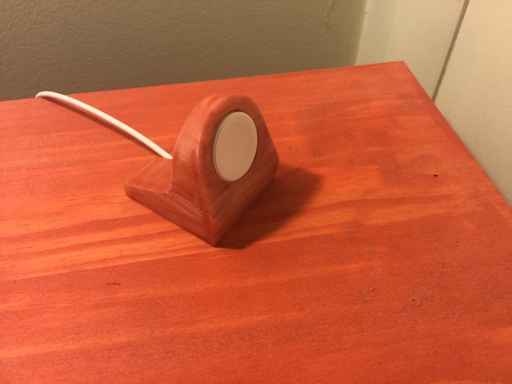
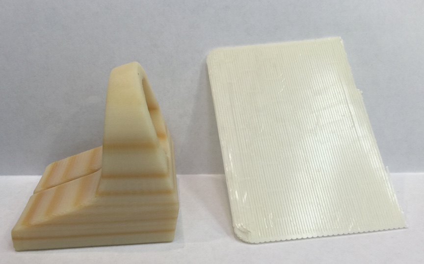
Just a very short follow up about my previous ABS post. I was able to paint the part with a brush and some IKEA BEHANDLA Glazing paint. This is the paint I used on my pine night-stands in 2012, so it is a little old, but it did the trick. The smooth surface on the bottom of the stand didn't hold paint very well, but that's okay. The textured sides where the printer slowly built up the part gave lots of surface area to color and it looks like it belongs. Happy accident, but worth remembering if you want a fake wood texture. You could even expose different parts of the roll of plastic intentionally for a very interesting color pattern, but go easy or you may hurt the plastic's integrity.
While researching about ABS damage from UV exposure, I found out that there are now UV sensitive plastic filaments available. The world of 3D printing moves very fast and I was apparently not up to speed on some of the new materials that are out there. Below is a video of the filament being exposed (not me or my filament obviously).
A little over a year ago I got a 3D printer. I've had a great experience with it! I had printed a lot of lab hardware and some fun things, but then let it sit around for a few months while things were very busy in other parts of work. This past week was maker week in State College, so there were lots of 3D printing demonstrations around town and other maker projects. I decided I should get things fired up again. I've got a couple of new projects that will need custom enclosures built. Without being able to have a spot-welder in my apartment, I'm pretty much limited to plastics or paying for the manufacturing.
I re-leveled and calibrated the bed and z-axis mechanism. I carefully re-checked the extruder calibration to be sure that I got the appropriate amount of plastic extruded. Everything looked great, so I downloaded a simple, but utilitarian part for my Apple Watch off thingiverse. Using Slic3r, I created the GCode and sent it off to print. Everything started off like normal, so I left the printer running to deal with other tasks. I came back later and too many surprise the part had stripes!
I've always printed with ABS plastic. It's not that I don't want to use PLA, it's just what I've always had on hand and what I know how to work with. I happened to have left the white roll of plastic on the printer after my last print. Since my printer sits next to the window, it gets some sunlight, especially in the morning hours. Not the best location, but it's the only location I can place it for the moment. It looks like the UV radiation has damaged my filament! Every time the part of the roll that was exposed heavily comes around, I get a band. For a simple charging stand, I'm not too upset. I could even try some of the ABS bleaching brews used by antique computer collectors. I may just paint the whole thing with paint that matches my wooden night stand. Maybe this will give me a false wood grain look?
I wanted to confirm that the stripes corresponded to a revolution of the spool. The whole part is darker than parts printed from the same roll months ago, but I'd guess the darker bits were on the top of the roll. By analyzing the GCode that produced the part, I calculated that the printed used about 5.1 meters of filament (<$2). The roll has been used down to a coiling diameter of about 150 mm. That means I expect about 10-11 turns of the reel for the print. I see 7-10 layers depending on what I count, so I'll call that close enough.
Well that's the story for now. Don't leave your ABS in the sunlight, even on your machine. I've been meaning to get a dust cover for the machine and this is even more reason to do so and make sure it's opaque.
This year at the fall meeting of the American Geophysical Union, I presented an education abstract in addition to my normal science content. In this talk, I wanted to raise the awareness of how easy it is to work with electronics and collect geoscience relevant data. This post is here to provide anyone that was at the talk, or anyone interested, with the content, links, and resources!
Sensors and microcontrollers and coming down in price thanks to mass production and advances in process technology. This means that it is now incredibly cheap to collect both education and research grade data. Combine this with the emergence of the "Internet of Things" (IoT), and it makes an ideal setup for educators and scientists. To demonstrate this, we setup a small three-axis magnetometer to measure the Earth's magnetic field and connected it to the internet through data.sparkfun.com. I really think that involving students in the data collection process is important. Not only do they realize that instruments aren't black boxes, that errors are real, and that data is messy, but they become attached to the data. When a student collects the data themselves, they are much more likely to explore and be involved with it than if the instructor hands them a "pre-built" data set.
For more information, watch the 5-minute talk (screencast below) and checkout the links is the resources section. As always, email, comments, etc are welcome and encouraged!
I recently received some money to purchase a 3D printer to aid my laboratory experiments. I thought that it would be good to share how I decided on the printer that I did and how hard/easy it was to setup. Currently I've only run a few simple test prints, but will be printing some mounting equipment for laboratory experiments within a few weeks.
Choosing a Printer
When choosing a printer, there are many factors to consider. The consumer 3D printer movement is still very young, so there are many different designs available that require different amounts of tinkering to work and have vastly different capabilities. To help decide, I made a few requirements and decision points :
1. I must be able to print something that is at least 8"x8"x8". Print area is an important consideration and is one of the biggest influences on cost. With this print size I can make most prototypes, brackets, etc that we need. Larger parts can always be printed in sections and joined, but it's not the strongest or easiest thing to do. 2. Print material and method. There are printers that can print in many types of plastic and even in wood. Some printers fuse plastic in layers in an "addictive manufacturing" process. Others can fuse a liquid into a plastic with a process referred to as stereo lithography. Most consumer level machines with a large print area are the type that extrude plastic. There is a large matrix of advantages and disadvantages, but we will just leave it at this for now. 3. The final factor I considered is the development of the machine. Informally this is the "tinker factor." How much are you willing to modify and experiment with the machine to get increased versatility vs. how much do you want a machine that is a push button that just works? I've always been the tinkering type but there is a balance. Some more experimental and low cost machines are not as reliable as I would prefer, but something that is fully developed like the MakerBot line doesn't leave as much versatility. The other portion is the licensing of the software and hardware. I've always been a proponent of the free and open source movement. It's how we are going to advance science and technology. Companies like MakerBot are not fully open source and that just doesn't sit well as it prevents the community from fixing problems in a piece of equipment that was rather expensive.
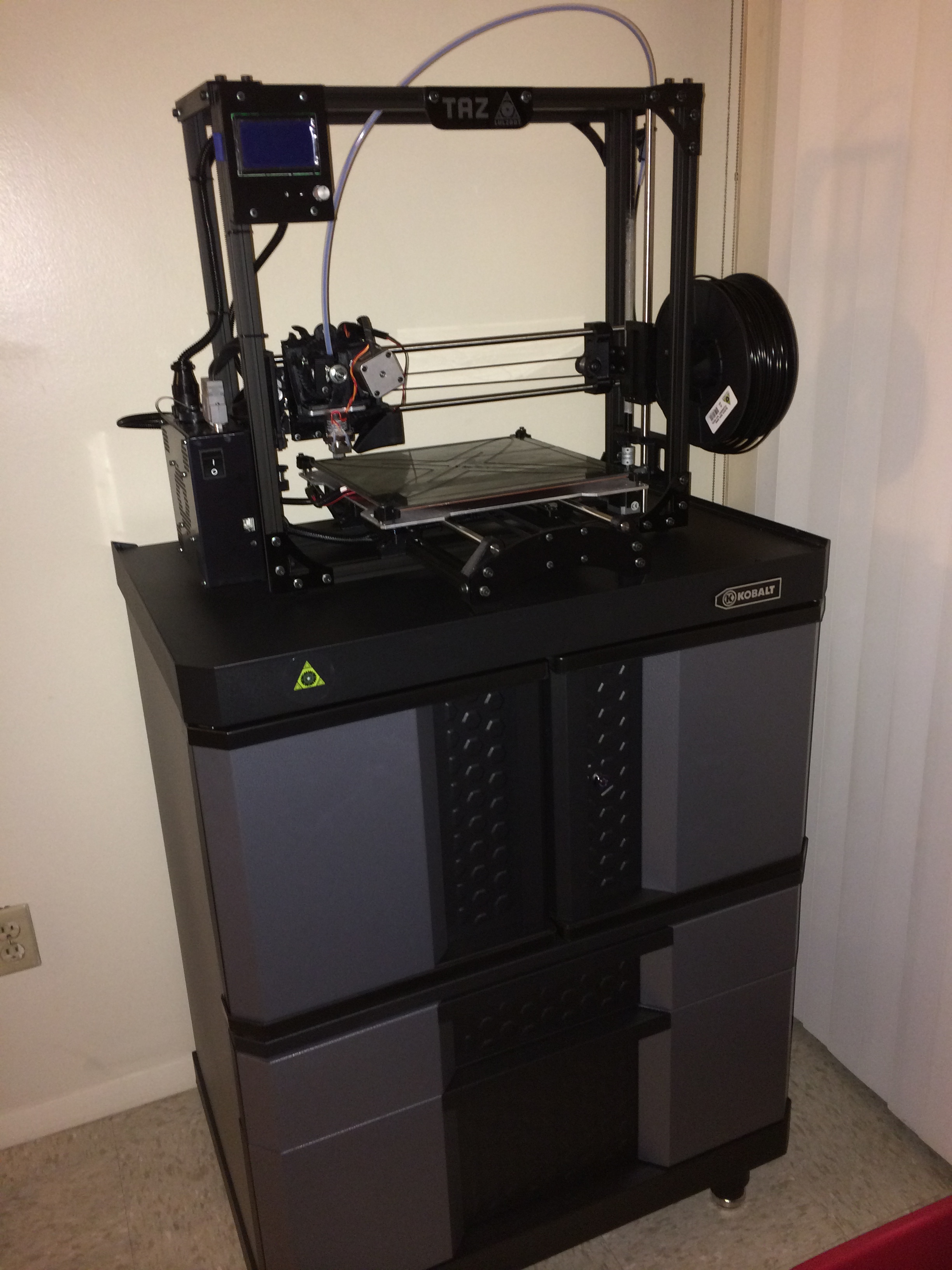
With all of those considerations and lots of research, I decided on the Taz 4 printer by Lulzbot. You can purchase the printer from Amazon, but I decided to purchase through Sparkfun Electronics since they are a small(ish) business that really supports education and the maker movement. I ordered the printer within a few hours of passing my comprehensive exams and it was on the way!
Setting up the printer
I received the printer and followed all of the setup instructions. This involved assembling the axes and removing the packing protection. I've never done this before, but overall it was very straightforward and took about 45 minutes. The next steps were what made me nervous.
To get quality prints the printer surface must be level with relation to the print head track. There are various end stops and leveling screws to adjust. Using a piece of printer paper as a gap gauge, I just followed the instructions and had the print bed leveled in about 20 minutes. There is also a test print pattern that prints two layers of plastic around the base plate to let you make sure the level is right on. Everything must be kept clean and adjusted as with any precision bit of gear, but overall I was impressed with the design.
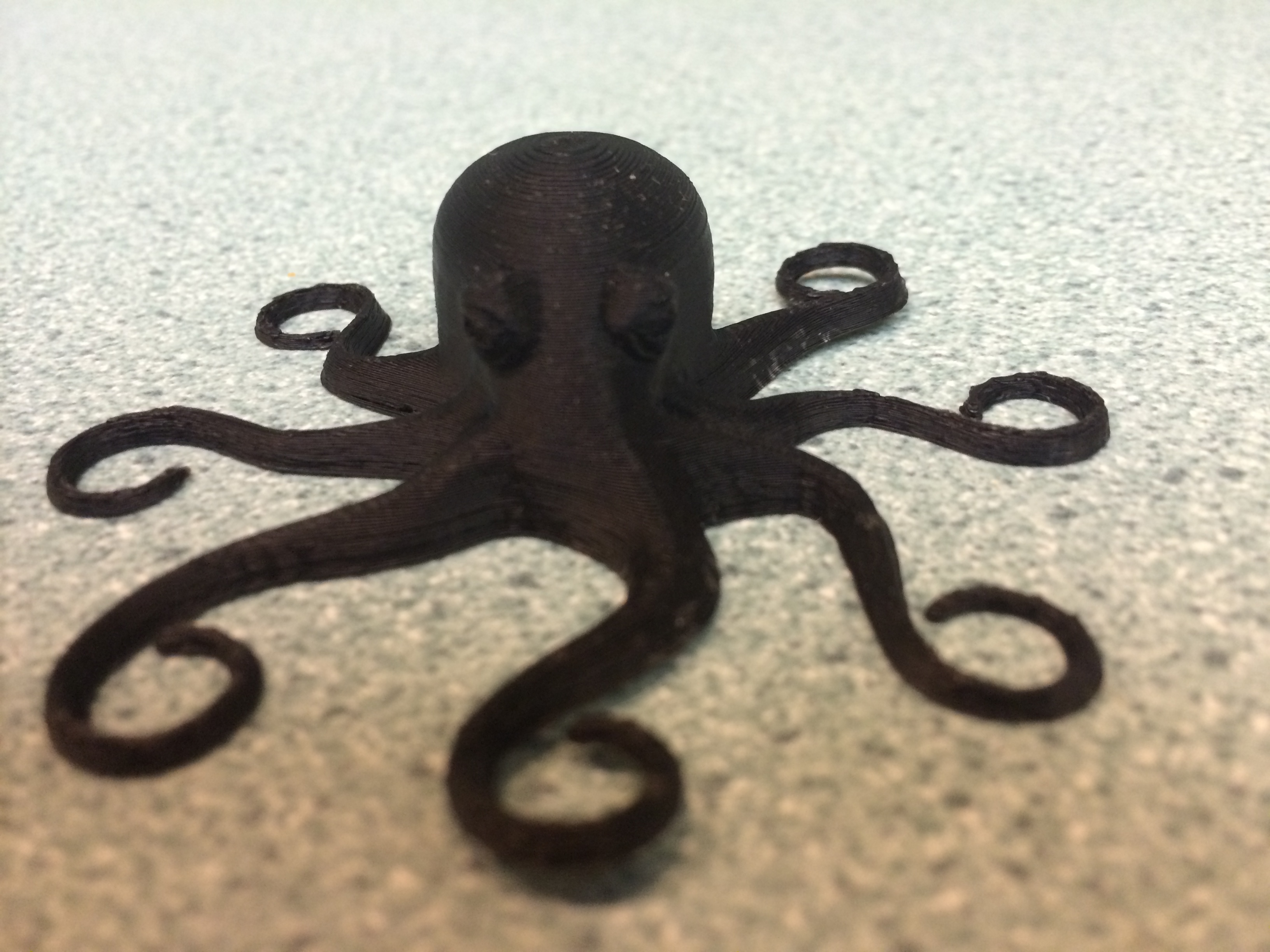
The printer ships with an octopus test print that was my first object. I loaded up the file and hit print. The printer ran for about an hour and at the end I had the print shown below!
What's Next
I've got some plans for what to print next. Currently I'm designing some new brackets to hold sensors in place during experiments and a few new parts like shields and pulleys to improve the quality of some of our demonstration apparatuses in the lab. I'm sure some of the results will end up as their own blog posts, but you can always see what's new by following me on Twitter (@geo_leeman). I also would like to thank Hess energy and Shell energy for their support of various aspects of these projects and of course the National Science Foundation for supporting me and many aspects of my lab research. Everything I've said is of course my own opinion and does not reflect the views of any of those funding organizations. Next post we will likely return to more general topics like seeing trends in data or go back and look at more Doppler radar experiments.
Update!
I was able to print my first laboratory parts, a set of brackets to make a magnetic holder for a displacement transducer. I will be posting the cad files to my github account under an open license.