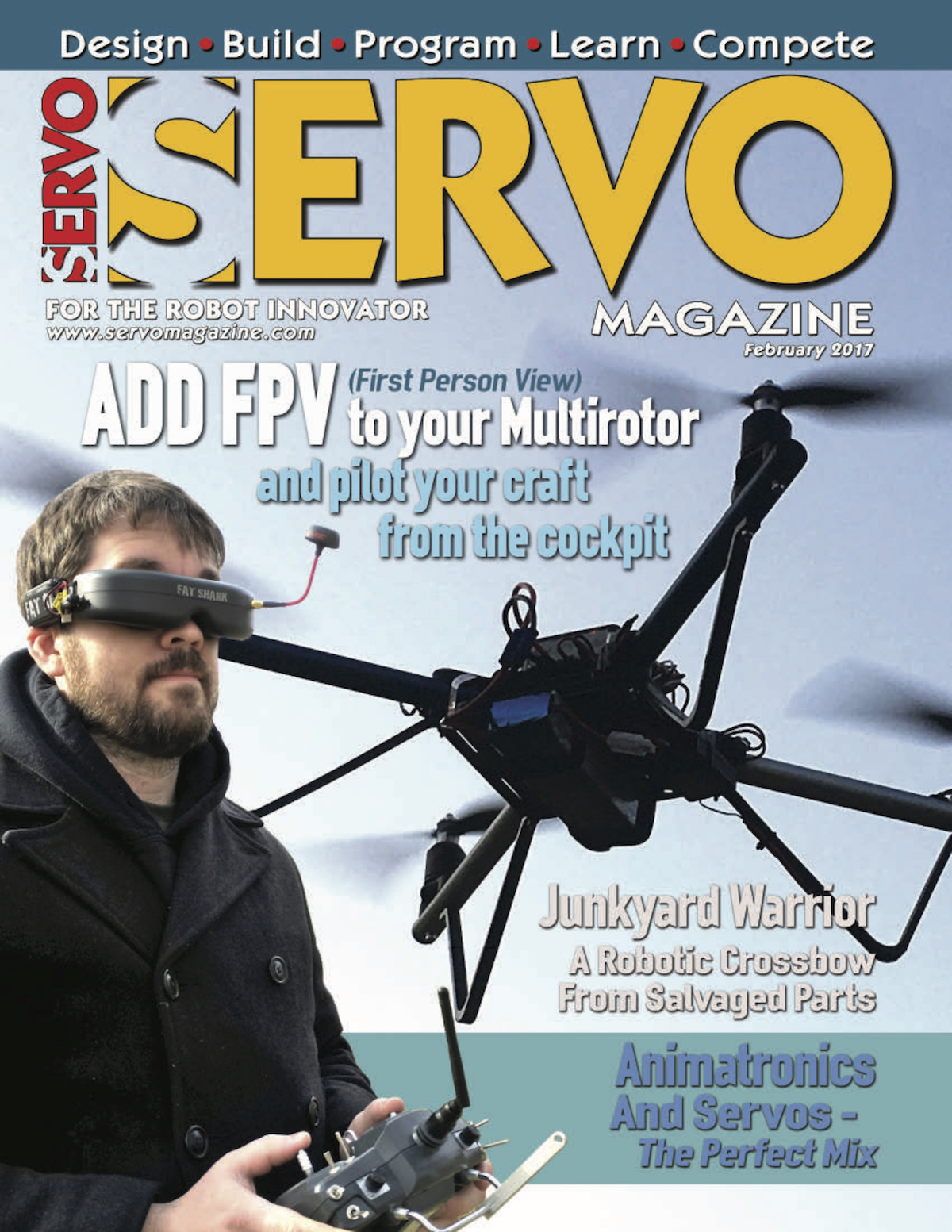
This month I was lucky enough to have a cover feature on adding a camera and googles/screen to your drone setup. Adding this "First Person View" (FPV) capability really makes flying a lot different as its like you are setting in the cockpit!
Several years ago, I rode in the copilot’s seat of a small Cessna circling over northwest Arkansas. The view was great and the experience of sitting right behind the propeller with a view of where we were headed was fantastic. It made riding in economy of commercial airliners seem even more boring and cramped than it already did. As multirotor pilots, we can now have that experience with first person view (FPV) equipment that literally puts us in the pilot’s seat and immerses us in the experience of flying.
Be sure to checkout the column and let me know of other topics you'd be interested in seeing in future articles! Right now I've got a photogrammetry series coming up after a quick CX-10 hack.
Things have been a bit slow here at the blog with a lot of things happening at work and the fact that I'm not also very excited to be writing a monthly column about multi-rotors in Servo Magazine! Not to worry though, I've still got some excellent projects queued up for the blog, including one that has currently filled my living room with sawdust.
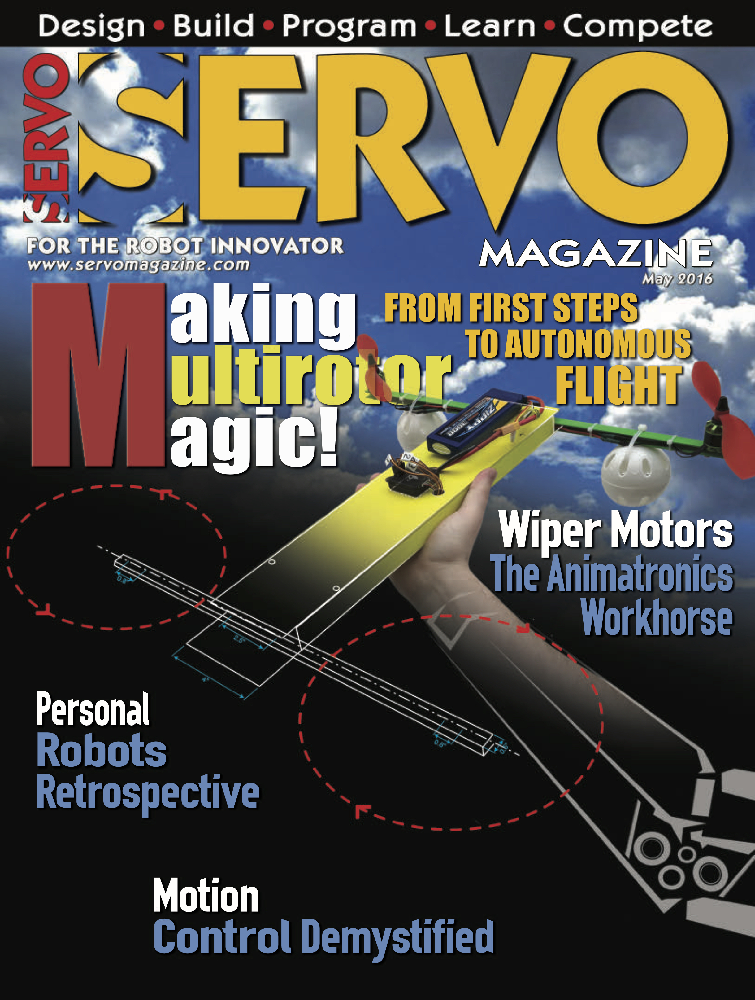
In this post, I wanted to share with you a video of the drone I scratch built flying around and encourage you to follow along and build it as well! The entire project cost about $350 and produced a really nice and versatile platform that I'm going to be adding instruments to, as well as GPS, telemetry, etc. The May issue of Servo featured the monthly column introduction on the cover! That column talks about FAA rules and how to get registered. The following columns are going to go through building the drone, step by step. We'll start off with the airframe, then move on to adding electronics, setting up the flight controller, and finally flying under manual and computer control. We already have other articles planned that include reviewing commercially available quads, as well as hardware hacking them for new functionality. If you like the blog, you might like to follow that series of articles as well!
While getting wedding arrangements ready a few months ago, my wife commented that she would like a Photo Booth at the wedding. I immediately did what I always do, write a Python script. She was thinking more of a table with props and disposable camera approach, but I decided to make it into a project that we could use on any occasion and have some fun with the Raspberry Pi.
I searched online thinking that surely somebody had already done this project and posted their code and instructions. I found a few examples of Pi based photo booth projects, but none that had code attached (mostly they said "my code is awful, so I won't share") and none that did exactly what I wanted. I wanted the booth to count down, take multiple photos of the guests, and store/tweet the photos. I also wanted it to be simple to plug in and turn on with no experience required - same for shutdown.
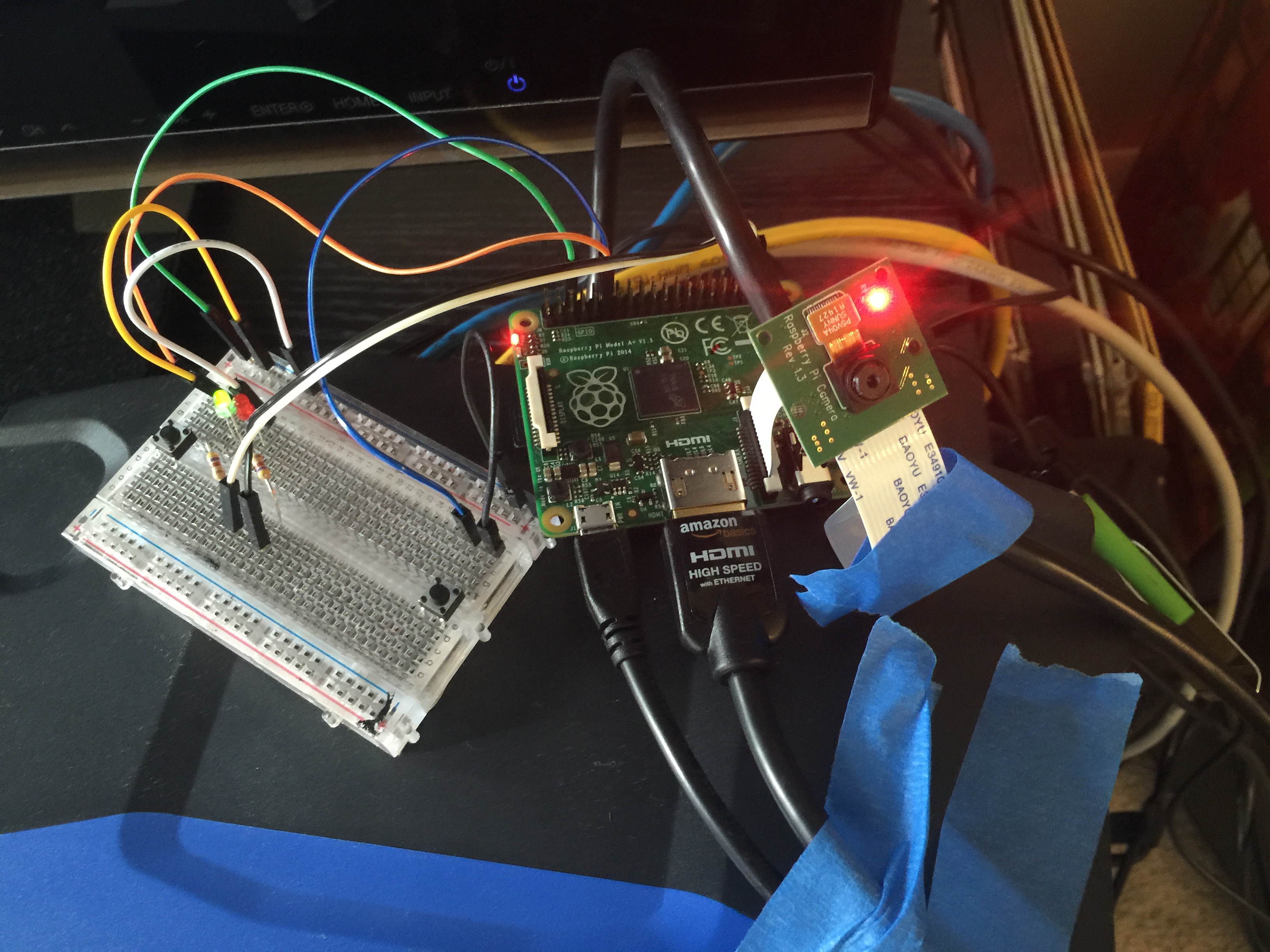
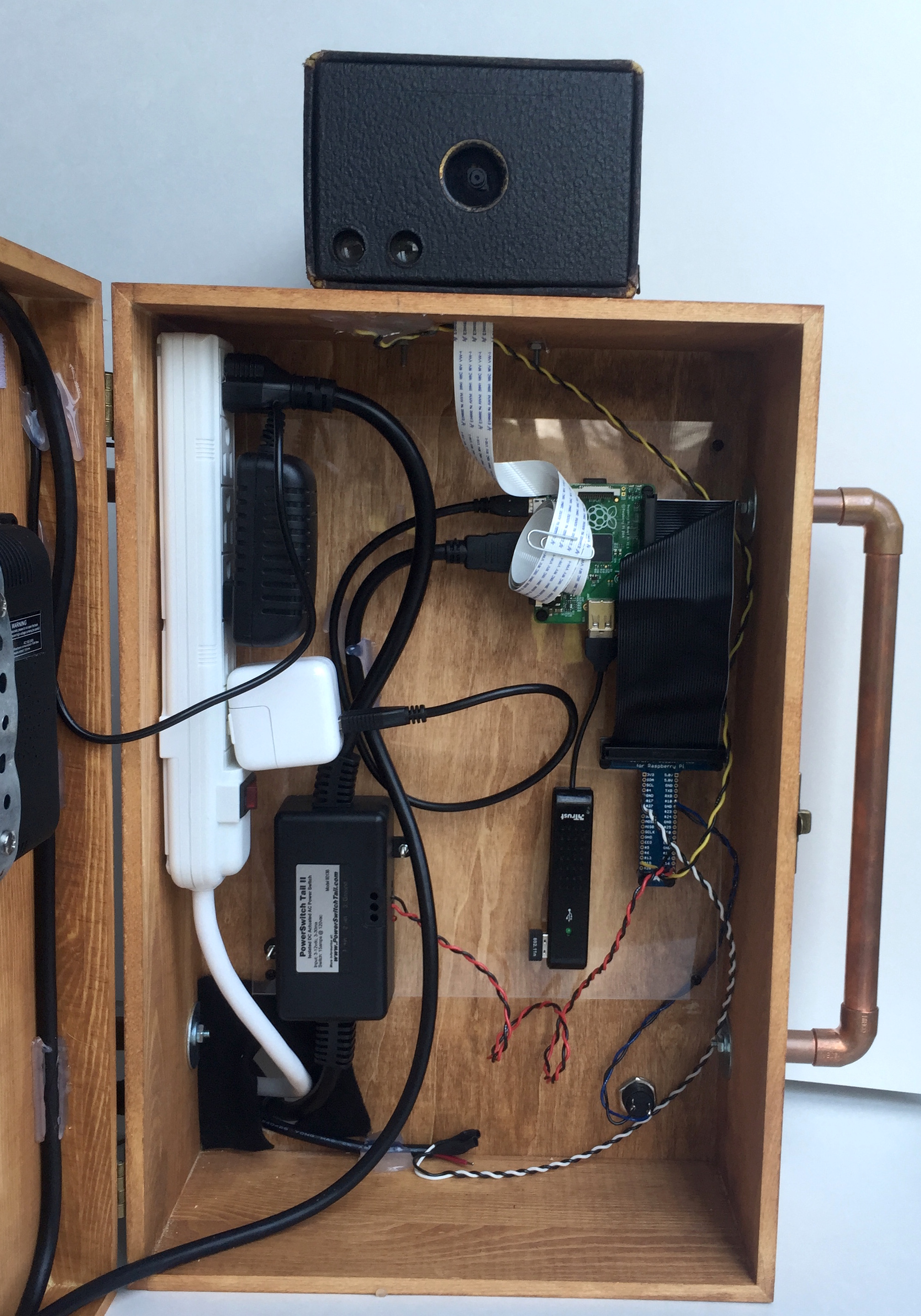
After a few afternoon coding sessions, I had the basic code and guts of the project working. A little time with some wood tools and I had a pretty decent looking enclosure setup as well!
An initial prototype circuit to test the code for the PiBooth.
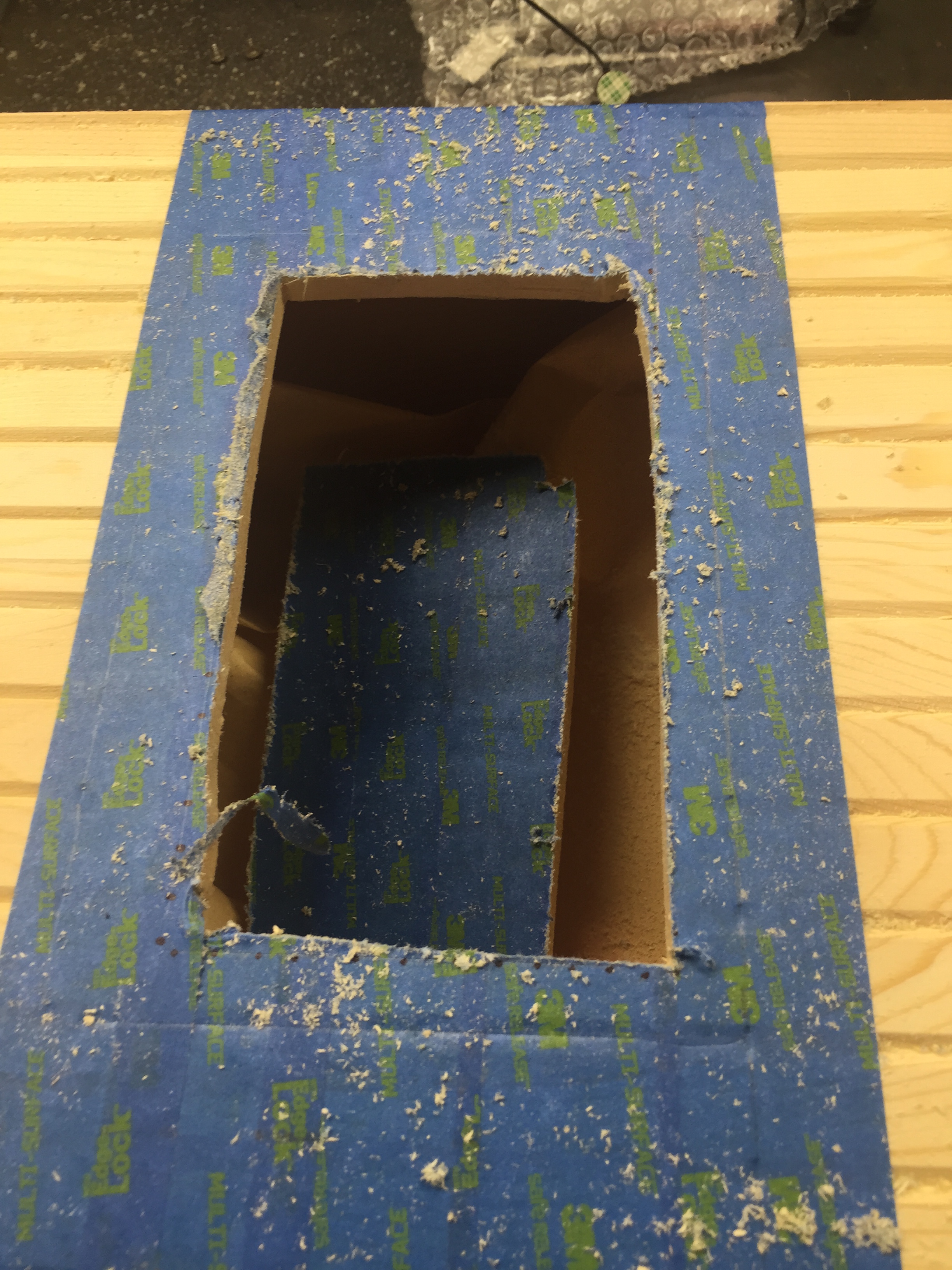
Rough cutting the hole for the photo booth screen in the shop.
I wanted to make sure that everything I did was out in the open to be reproduced. I ended up deciding to try writing a magazine article about the build for the electronics hobbyist magazine "Nuts and Volts." The editor sent me some guidelines and after a few hours I had a draft article. A couple of months passed by while we iterated on figures and ideas, but I was very excited when I was contacted saying that this article was being considered for the cover of the March 2016 issue. As you can see - it was selected! Be sure to grab a copy of Nuts and Volts (check your bookseller/news-stand) and read all of the details. You can grab the code over on the GitHub repository. Thank you to all the wonderful folks at the magazine for making this happen and thank you to my wife for letting me run wild with this project! Let me know if you build one, or a variant. The applications can range from parties/events to making an automated I.D. card station for your company!
As frequent readers of the blog or listeners of the podcast will know, I really like doing outreach activities. It's one thing to do meaningful science, but another entirely to be able to share that science with the people that paid for it (taxpayers generally) and show them why what we do matters. Outreach is also a great way to get young people interested in STEAM (Science, Technology, Engineering, Art, Math). When anyone you are talking to, adult or child, gets a concept that they never understood before, the lightbulb going on is obvious and very rewarding.
Our lab group recently participated in two outreach events. I've shared about the demonstrations we commonly use before when talking about a local science fair. There are a few that probably deserve their own videos or posts, but I wanted to share one in particular that I improved upon greatly this year: Squeezing Rocks.
Awhile back I shared a video that explained how rocks are like springs. The normal demonstration we used was a granite block with strain gauges on it and a strip chart recorder... yes... with paper and pen. I thought showing lab visitors such an old piece of technology was a bit ironic after they had just heard about our lab being one of the most advanced in the world. Indeed when I started the paper feed, a few parents would chuckle at recognizing the equipment from decades ago. For the video I made an on-screen chart recorder with an Arduino. That was better, but I felt there had to be a better way yet. Young children didn't really understand graphs or time series yet. Other than making the line wiggle, they didn't really get the idea that it represented the rock deforming as they stepped on it or squeezed it.
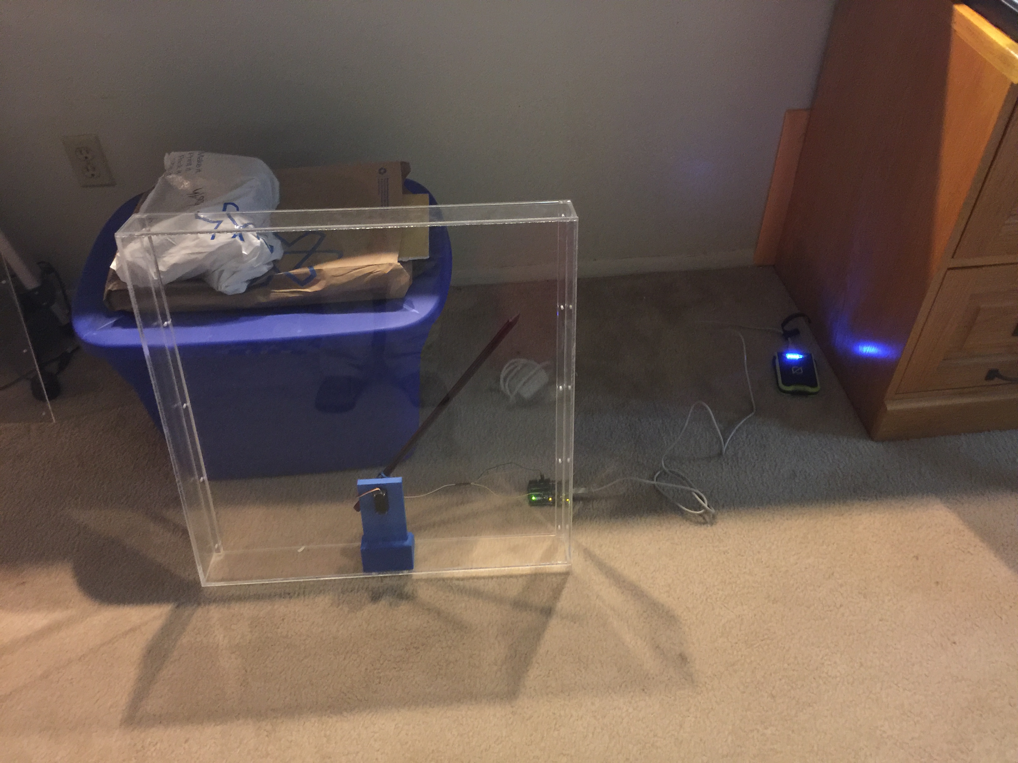
I decided to go semi old-school with a giant analog meter to show how much the rock was deformed. I wanted to avoid a lot of analog electronics as they always get finicky to setup, so I elected to go with the solution on a chip route with a micro-controller and the HX711 load cell amplifier/digitizer. For the giant meter, I didn't think building an actual meter movement was very practical, but a servo and plexiglass setup should work.
A very early test of the meters shows it's 3D printed servo holder inside and the electronics trailing behind.
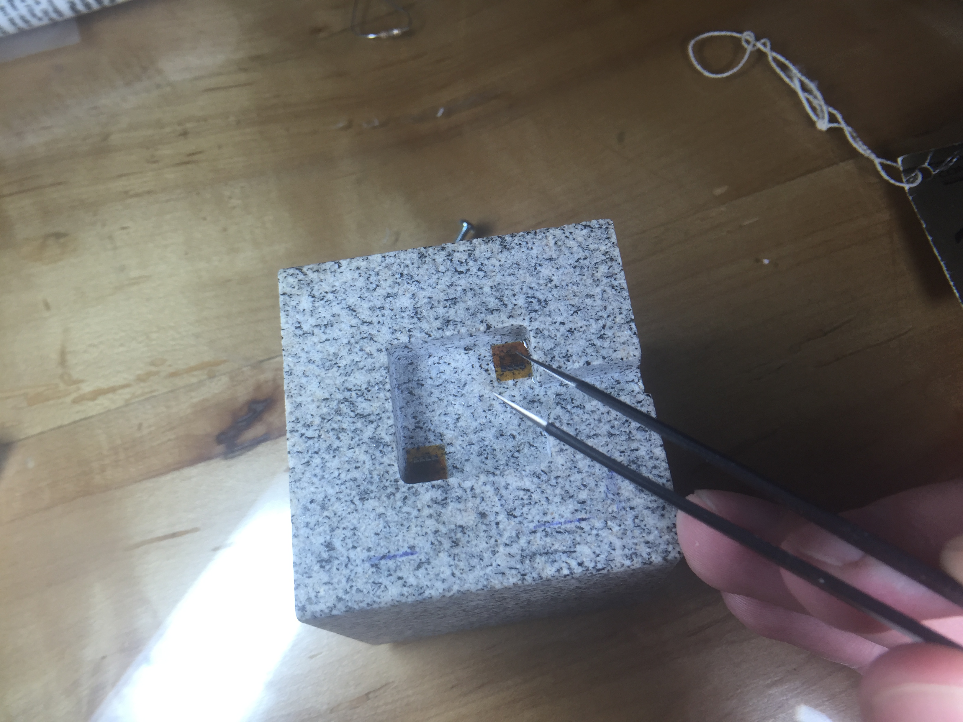
Another thing I wanted to change was the rock we use for the demo. The large granite bar you stepped on was bulky and hard to transport. I also though squeezing with your hands would add to the effect. We had a small cube of granite about 2" on a side cut with a water jet, then ground smooth. The machine shop milled out a 1/4" deep recess where I could epoxy the strain gauges.
Placing strain gauges under a magnifier with tweezers and epoxy.
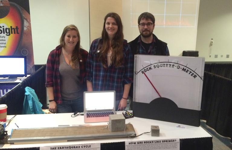
Going into step-by-step build instructions is something I'm working on over at the project's Hack-a-Day page. I'm also getting the code and drawings together in a GitHub repository (slowly since it is job application time). Currently the instructions are lacking somewhat, but stay tuned. Checkout the video of the final product working below:
The demo was a great success. We debuted it at the AGU Exploration Station event. Penn State even wrote up a nice little article about our group. Parents and kids were amazed that they could deform the rock, and even more amazed when I told them that full scale on the meter was about 0.5µm of deformation. In other words they had compressed the rock about 1/40 the width of a single human hair.
A few lessons came out of this. Shipping an acrylic box is a bad idea. The meter was cracked on the side in return shipping. The damage is reparable, but I'm going to build a smaller (~12-18") unit with a wood frame and back and acrylic for the front panel. I also had a problem with parts breaking off the PCB in shipment. I wanted the electronics exposed for people to see, but maybe a clear case is best instead of open. I may try open one more time with a better case on it for transport. The final lesson was just how hard on equipment young kids can be. We had some enthusiastic rock squeezers, and by the end of the day the insulation on the wires to the rock was starting to crack. I'm still not sure what the best way to deal with this is, but I'm going to try a jacketed cable for starters.
Keep an eye on the project page for updates and if any big changes are made, you'll see them here on the blog as well. I'm still thinking of ways to improve this demo and a few others, but this was a giant step forward. Kids seeing a big "Rock Squeeze O Meter" was a real attention getter.
Hmm... As I'm writing this I'm thinking about a giant LED bar graph. It's easy to transport and kind of like those test your strength games at the fair... I think I better go parts shopping.
While home for the holidays, I decided to make a little calibration stand that I need for a tilt meter project I'm working on. Back in the 2006 time frame I had worked to learn basic machining skills on the mill and lathe. I never was amazing at it, but managed to get a basic skill set down. I ended up back over at my mentor's shop this week to make a simple part, but thought you may enjoy seeing some photos of a simple milling setup.
The first step is to have a part design that is exactly what you want to make. Problems always arise when you have a rough sketch and make it up as you go. For some hobby projects that can work, but as our systems become more and more complex, it generally just leads to wasted time, material, and lots of frustration. This particular part is exceedingly simple, but I went ahead and made a full 3D CAD model anyway, just to illustrate the process.
Our goal is to make a flat plate for a tilt meter to set on. We will then elevate one end of the plate a known amount with precision thickness pieces of metal called gauge blocks. Knowing the distance between the ends of the plate and the amount we elevate one end, we can very accurately calculate the angle. That lets me calibrate the readings from the tilt meter to real physical units of degrees or radians. All good designs start with a specification, my specification was I wanted at least 5 different tilts ranging from 0 - 0.5 degrees, the more combinations possible the better. I also wanted a compact and rigid device that wouldn't bend, warp, or otherwise become less accurate when tilted.
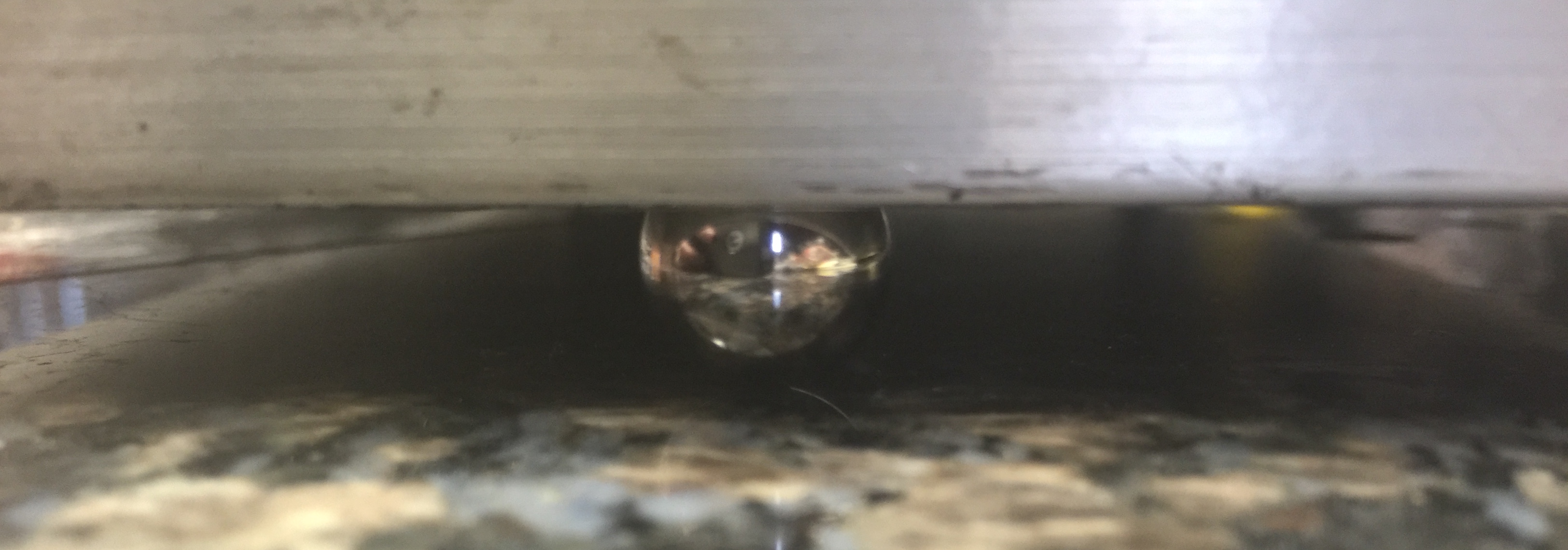
Time to fire up a Jupyter notebook and do some calculations! I mainly wanted to be able to play with the tradeoffs of baseline length, height of gauge block (they come in standard sizes), etc. After playing with the numbers some, I came with up a design that used multiple baseline lengths with available gauge blocks. I decided to use ball bearings under the plate to give nice point contacts with the surface of the table as well. This meant I needed a plate about 6" x 12" with hemispherical divots to retain the bearings.
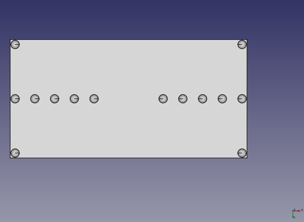
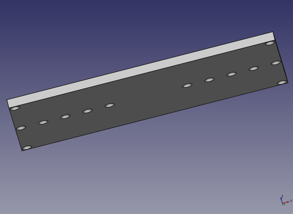
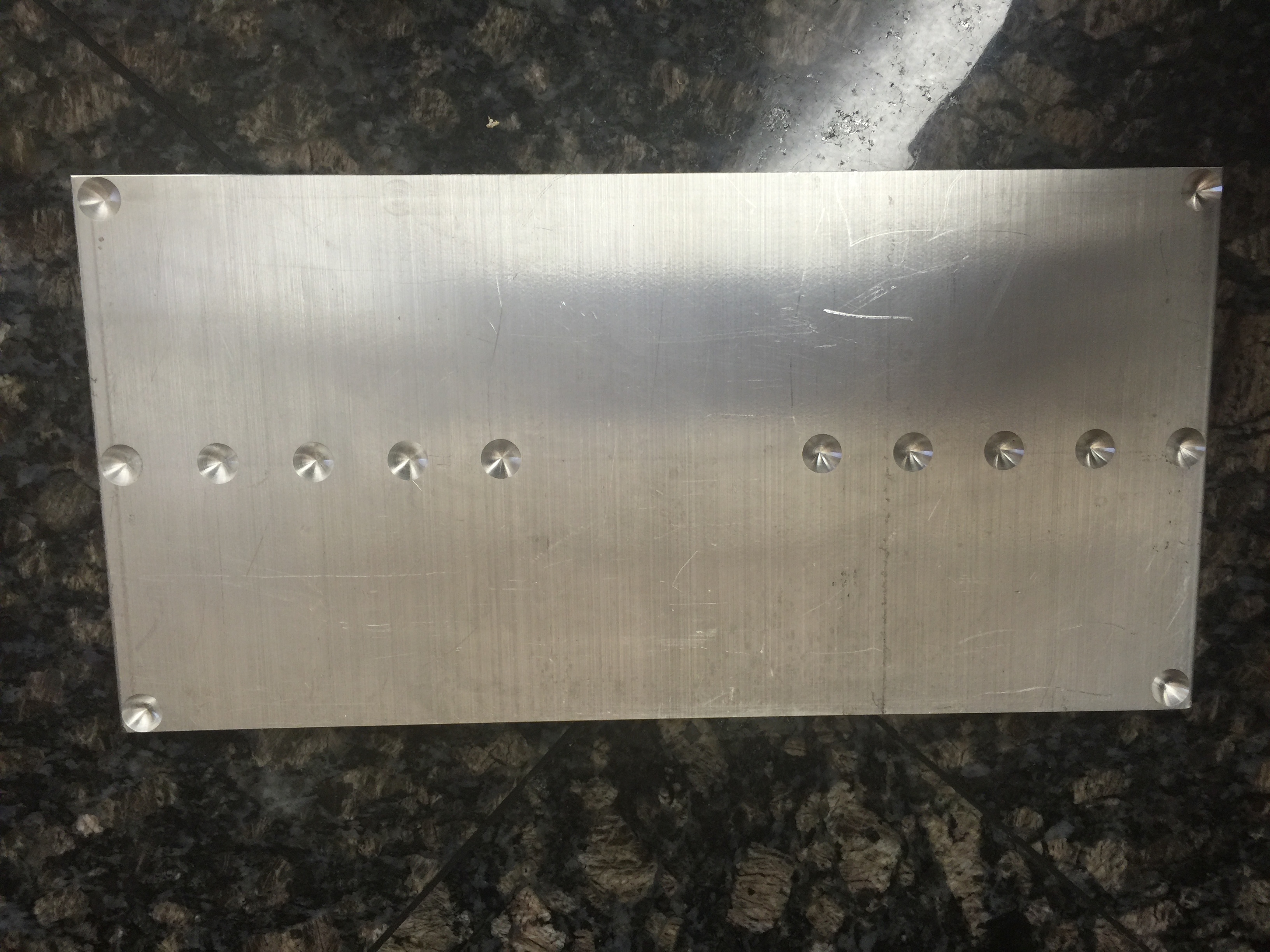
Next, I fired up FreeCAD and made the design by taking a 6" x 6" plate and using 0.5" spheres as the cutting shape to make the divots. The divots are only 1/8" deep, so setting them in 1/4" from the edges is enough. Then I just mirrored that 6" x 6" part to make the full part. This lets me tilt both directions the same amount without turning or moving the instrument under test. The drawing I produced is shown in both bottom and oblique view.
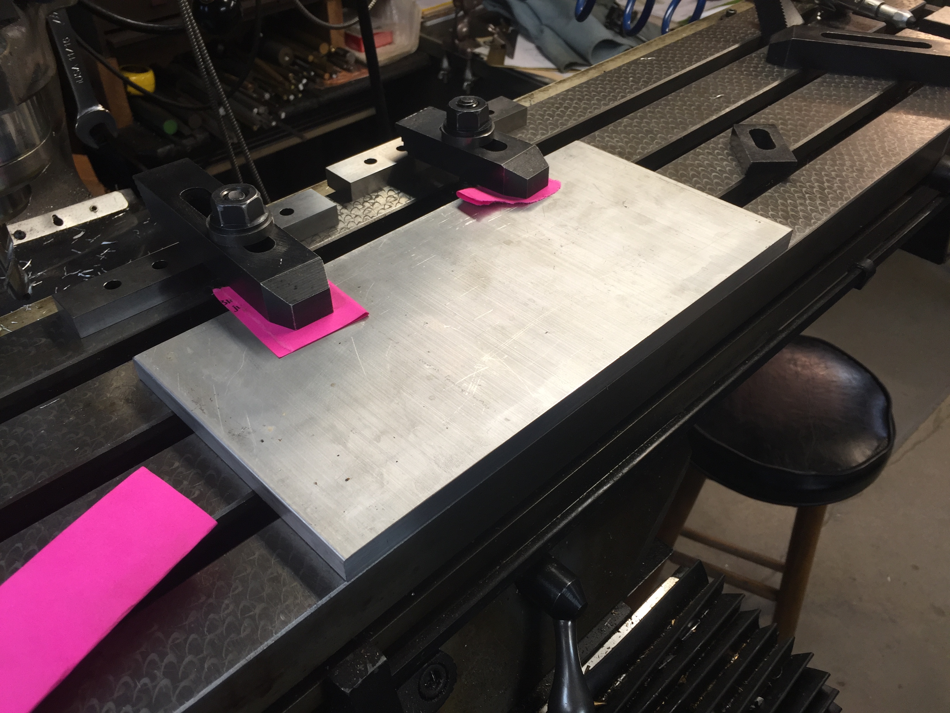
Next it was time to make the plate. I ended up with a piece of 0.5" thick 6061 Aluminum plate. We first cut it to roughly the size we wanted (slightly oversized) with a bandsaw. Then the plate was clamped down to the milling machine table to take off the extra material with a milling bit and give the sides a nice and clean finish. We ended up re-clamping during the work (almost always a bad idea) and had a slight taper on the width, but that isn't a concern for the usefulness. (By slight taper I mean about 20 thou along the length.)
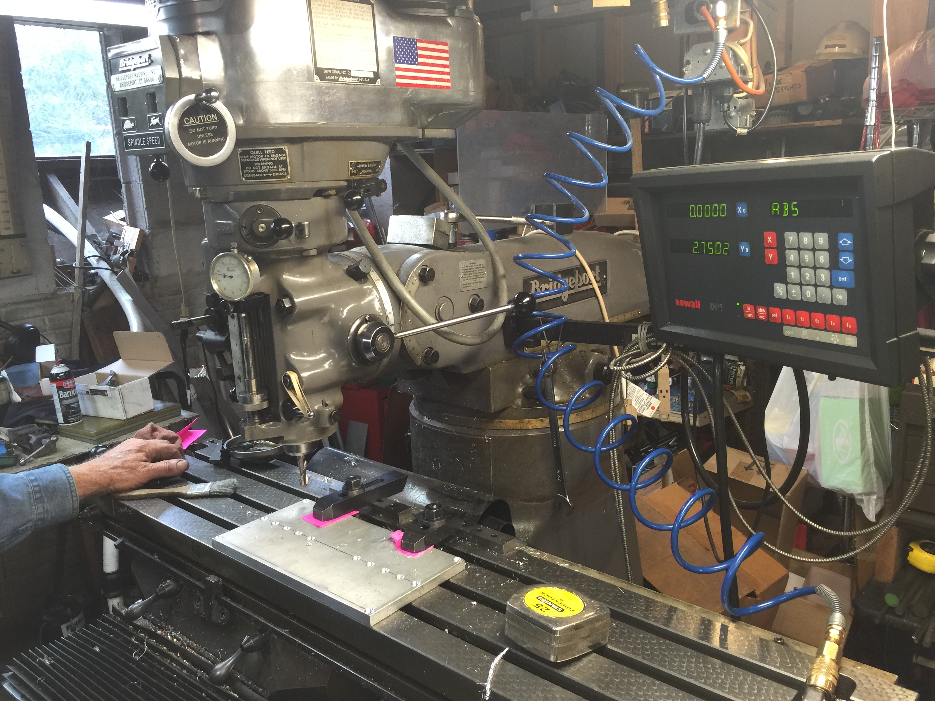
We then were ready to make the divots. To do this we used a ball end mill that makes nice hemispheres. This is a very simple part, so just finding the edge, setting the readout, and doing the cuts took about 20 minutes. I've included some photos incase you haven't seen a milling setup before. It's really great fun to be able to control these cutters and tools to a thousandth of an inch and sculpt metal into what you need. As I said, this isn't a complex part, but that's good because I was a little rusty!
In the end we got a nice plate and I think it will perform its duty very well. I'll most likely write a future post showing it in use and explaining instrument calibration. I've included some pictures of the finished plate and how it will work sitting on the ball bearings.
I was printing some parts and kept having issues with the layers coming apart and/or having a bubbly, uneven surface texture. I generally print with ABS plastic, even though others seem to have more issues with it, I've always had better luck than with PLA. I decided to try some PLA and also had problems with it sticking and with the filament becoming very brittle and shattering. This problem was slowly driving me crazy as I usually can get high quality prints with little fuss.
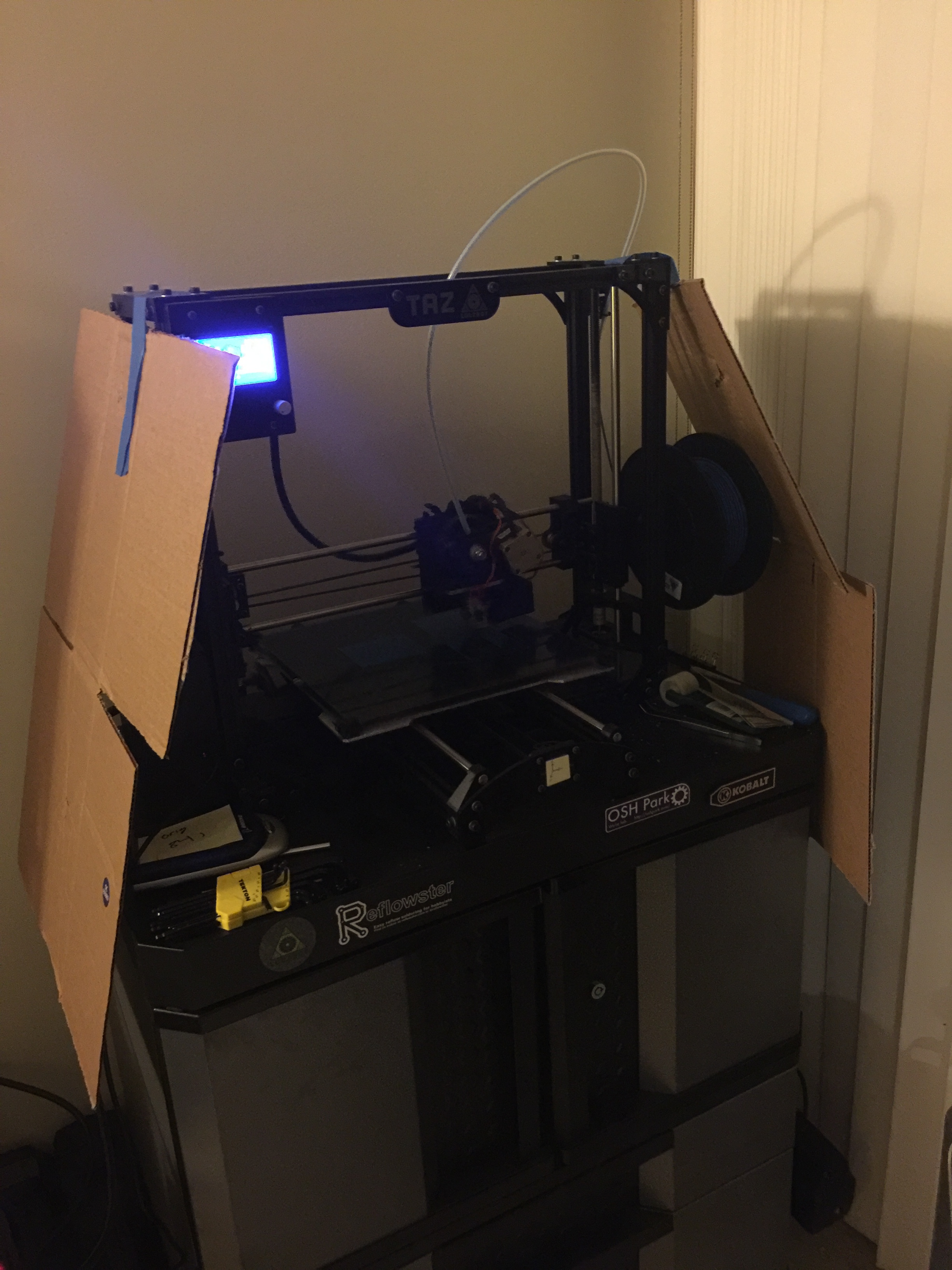
First off I moved the printer further away from the window to be sure no hot/cold convective air currents were interrupting the printing process. I even hung some cardboard sheets around the side of the print area. If I had the space I'd make a full enclosure for the printer to cut off all air currents from the room, but that will have to wait for awhile. (It would also dampen the noise, which is a bonus in an apartment!) I still was getting "bubbly" prints though.
Cardboard baffles taped onto the printer in an effort to reduce air currents near the print surface.
After reading more online I decided that my filament must be too moist. The plastic is adsorbing moisture from the humid air and that turns to steam in the print head, causing little blow-outs and my bubbly texture. After consulting with a colleague that does a lot of printing, he confirmed that this is an issue and even cited his tests showing that filament over a few weeks old produced weaker prints. There are a few ways I can think of to help with the issue: 1) put filament in a bucket with a light bulb as a heater to keep the humidity low, 2) keep the filament in vacuum packs, 3) lock it in a low humidity environment with silica gel beads. Based on cost and convenience, I ended up going with the third option. While this technique won't give filament an infinite life, I was hoping to salvage some of mine.
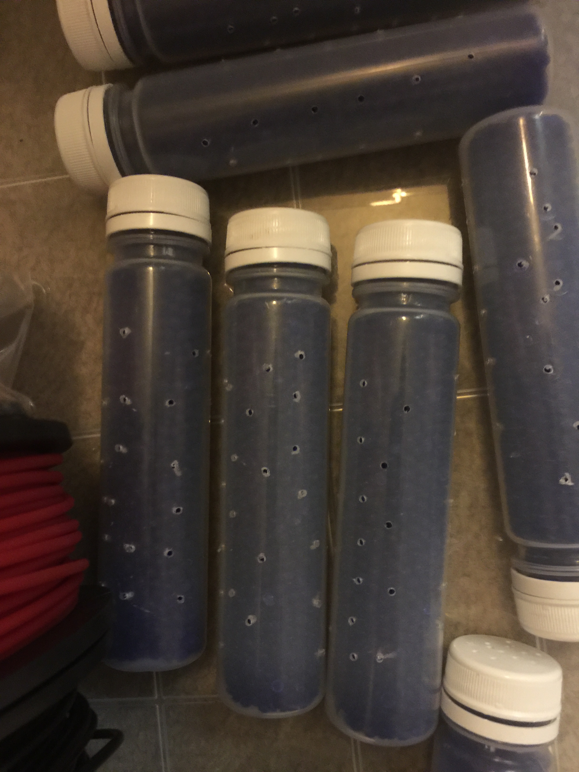
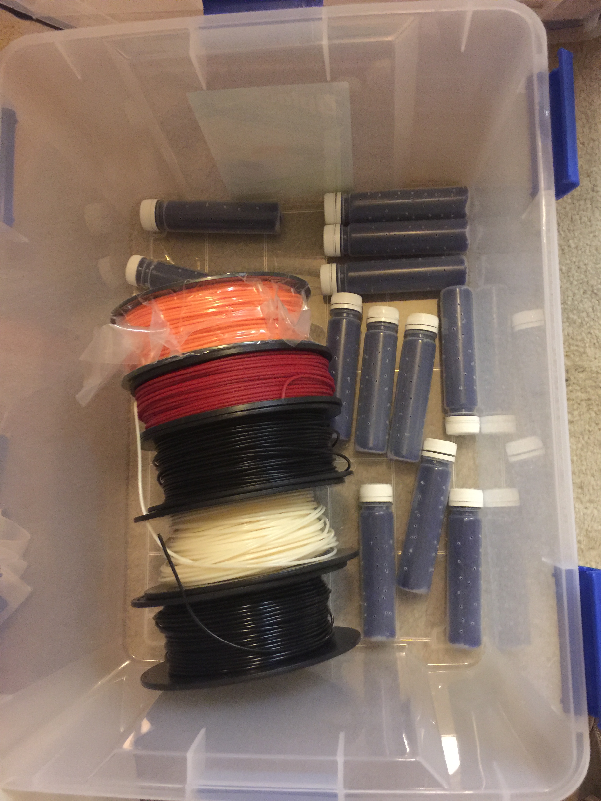
I went to a craft store and bought a plastic tub that had a soft air/water tight seal; specifically the Ziploc Weathertight series container. I also ordered a gallon container of silica beads that are commonly used to keep products dry during shipping. While the products were on their way, I collected a bunch of plastic containers and drilled many small holes in them. When the beads arrived I filled the containers with them and placed them and my filament in the large box.
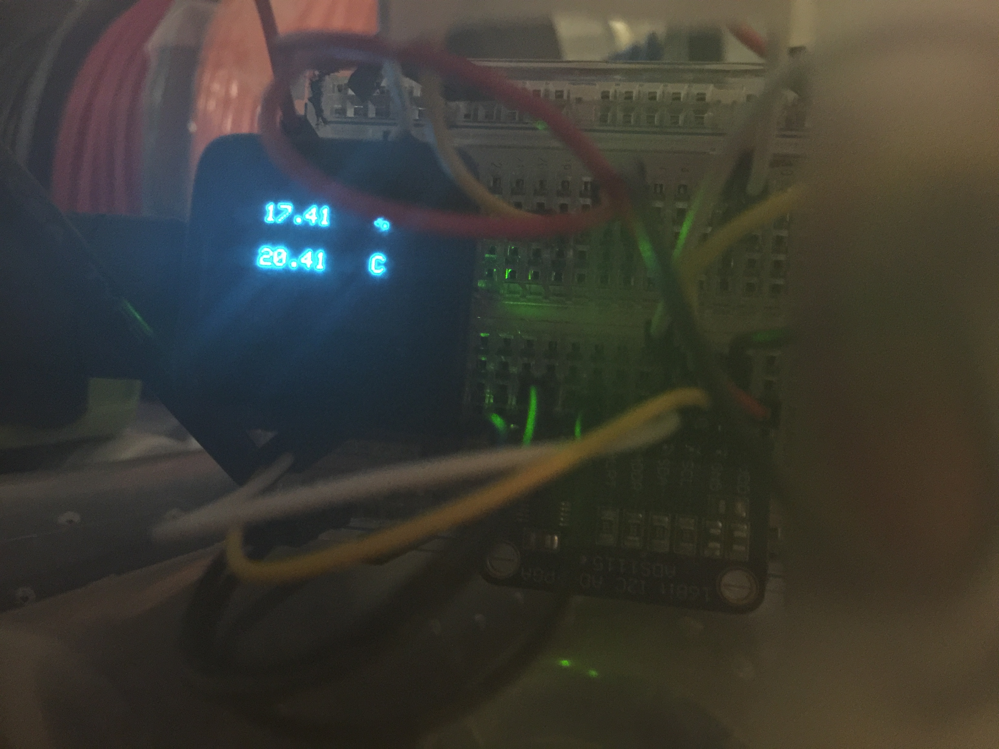
In an effort to see how good of a job the silica beads were doing, I also taped a humidity indicator inside the box. I hadn't used these simple indicators before and had no idea how accurate they were, so I whipped up a quick sensor with a MicroView (Arduino) and checked it. To my surprise, it was dead on, even when exposed to the higher room humidity. If you only need 5-10% accuracy (like when seeing if the silica beads need to be baked because they are saturated) these seem to do the trick.
A close-up of the microview showing 17% RH inside my container.
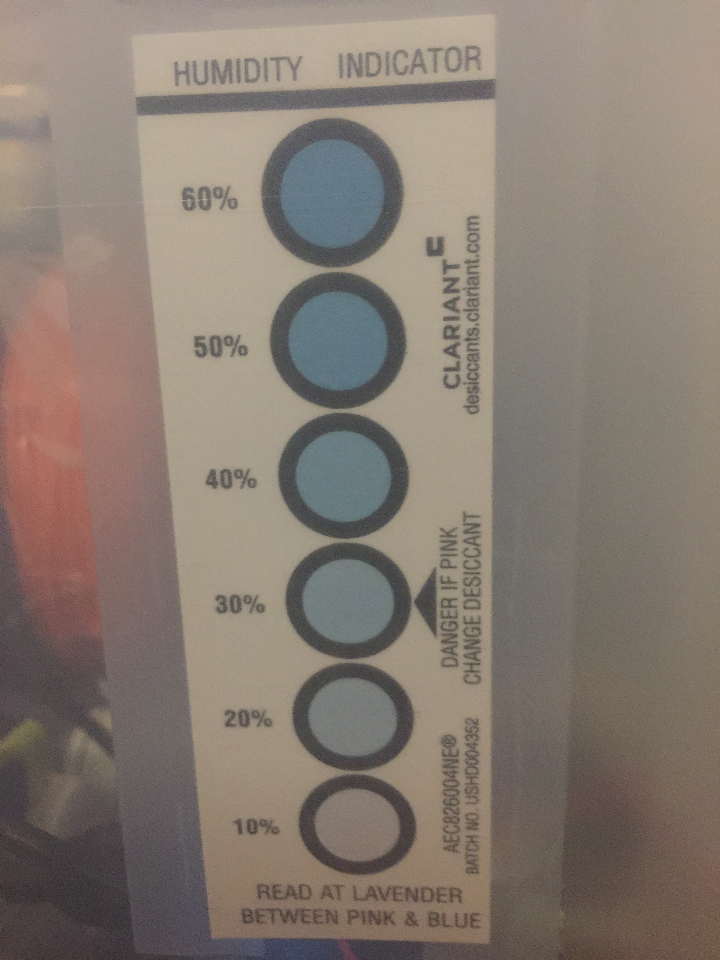
The humidity indicator also shows below 20%, matching the electronic sensor.
Once I verified that this solution might work, I put the rest of the filament and anything else I wanted to stay dry in the tub. Still lots of room left for future filament purchases, unpainted parts, and all of the surface mount sensors that need to be stored in a dry environment.
After letting the filament sit in the box for a few days, I tried another print. To my surprise, there were no more blow-outs! I still have a problem with part of my print bed not adhering very well, but that's another story and another, currently only partially solved, mystery. For now, this box solution seems to have part of my 3D printing problems solved. I have noticed that old filament does produce weaker prints, so I'm going to start stocking less filament and print most things in a single color (probably just black and white unless a special need arises).
I've been working on developing some geophysical instruments that will need some significant temperature compensation. Often times when you buy a sensor there is some temperature dependance (if not humidity, pressure, and a slew of other variables). The manufacturer will generally quote a compensation figure. Say we are measuring voltage with an analog-to-digital converter (ADC); the temperature dependance may be quoted as some number of volts per degree of temperature change over a certain range of voltages and temperatures. Generally this is a linear correction. Most of the time that is good enough, but for scientific applications we sometimes need to squeeze out every error we can and compare instruments. Maybe one sensor is sightly more temperature dependent than another; comparing the sensors could then lead us to some false conclusions. This means that sometimes we need to calibrate every sensor we are going to use. In the lab I work in, we calibrate all of our transducers every 6 months by using transfer standards. (Standards, transfer of standards, and calibration theory are a whole series of posts in themselves.)
To do thermal calibrations it is common to put the instruments into a thermal chamber in which we can vary the temperature over a wide range of conditions while keeping the physical variable we are measuring (voltage, pressure, load, etc) constant. Then we know any change in the reading is due to thermal effects on the system. If we are measuring something like tilt or displacement, we have to be sure that we are calibrating the electronics, not signals from thermal expansion of metals and materials that make up our testing jig.
I scoured EBay and the surplus store at our University, but only found very large and expensive units. I remembered that several years ago Dave Jones over at the EEVBlog had mentioned a cheap alternative made from a peltier device wine cooler. I dug up his video (below) and went to the web again in search of the device.
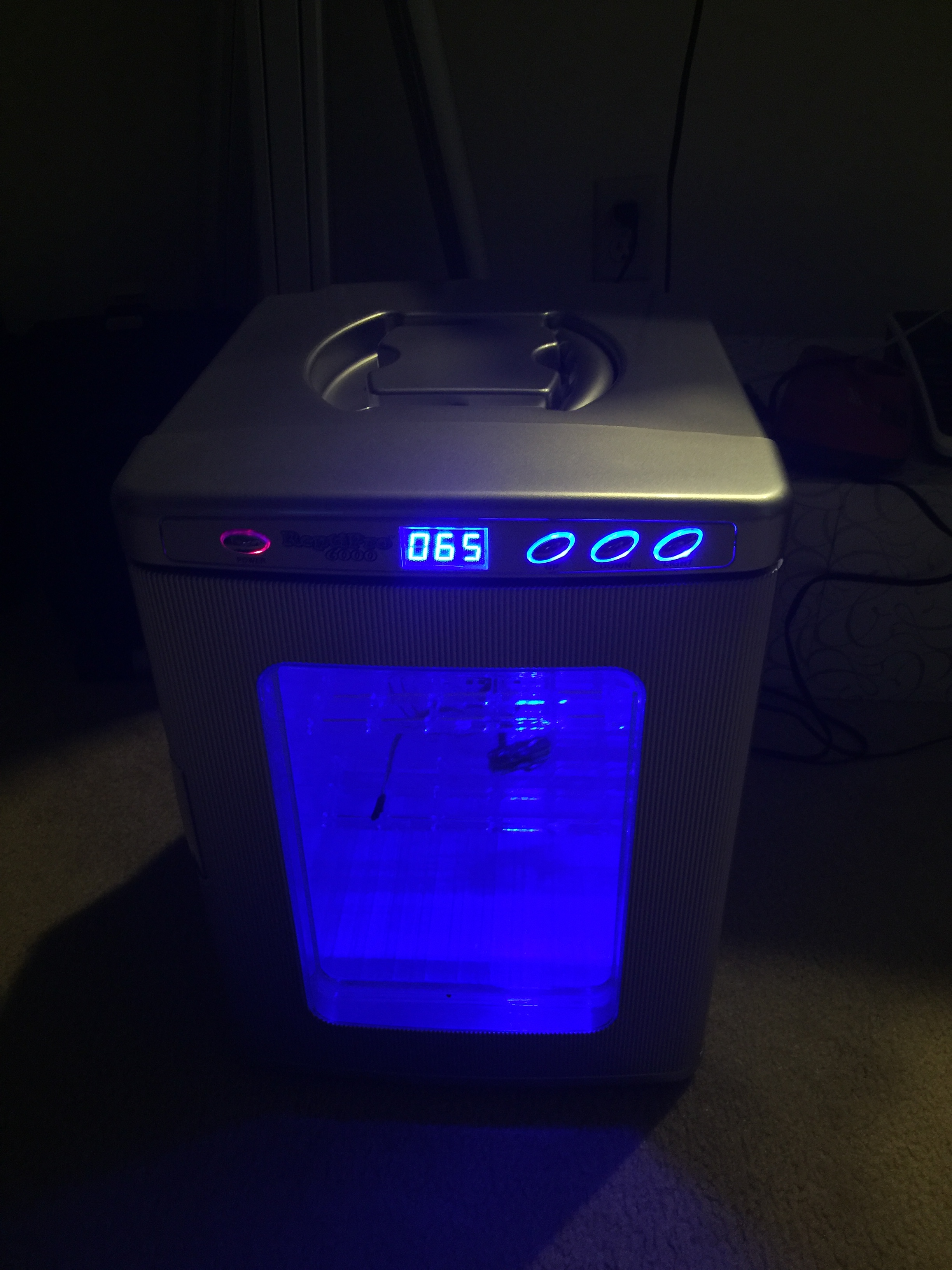
I found the chamber marketed as a reptile egg incubator on Amazon. The reviews were not great, some saying the unit was off by several degrees or did not maintain the +/- 1 degree temperature as marketed. I decided to give it a shot since it was the only affordable alternative and if it didn't work, maybe I could hack it with a new control system and use the box/peltier element with my own system. In this post I'm going to show you the stock performance of the chamber and some initial tests to figure out if it will do the job.
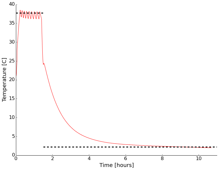
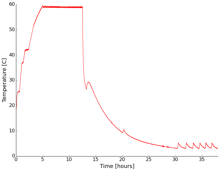
As soon as it arrived I setup the unit and put an environmental sensor in (my WxBackpack for the Light Blue Bean used back in the drone post) inside. I wanted to see if it was even close to the temperature displayed on the front and how good the control was with no thermal load inside. There was a small data drop-out causing a kink early in the record (around 30 C). It looks like the temperature is right on what I had set it to with the quoted +/- 1 degree range. There is some stabilization time and the mean isn't the same as the set point, but that makes sense to me, you don't want to overheat eggs! This looks encouraging overall. I also noticed that the LED light inside the chamber flickered wildly when the peltier device was drawing a lot of power heating/cooling the system. I then opened the door and set the unit to cool. After reaching room temperature, I closed the door and went to bed. It certainly isn't fast, but I was able to get down to about 2C with no thermal load. That was good enough for me. Time to add a cable port, checkout the LED issue, and test with some water jars for more thermal mass.
Initial test of the thermal chamber with nothing inside except a temperature logger. Set point shown by dashed line.
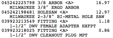
The next step was to add a cable port to be able to get test cables in and out. I decided to follow what Dave did and add a 1.5" test port with a PVC fitting, a hole saw, and some silicone sealant. Below are a few pictures of drilling and inserting the fitting. I used Home Depot parts (listing below). I didn't have the correct size hole-saw. That's happened a lot lately, so I invested in the Milwaukee interchangeable system. I got a threaded fitting so I can put a plug in if needed. the time honored tradition is to put your cables through the port and stuff a rag in though. This works as well as a plug generally, but it's nice to have the option.
Before, during, and after cable port placement. The center of the hole is 7 3/8" back from the front door seal, and 5 1/8" up from table top level. I used gel super glue to quickly fix the fitting to the plastic layers and foam. After that dried, I used silicone bath adhesive/sealant to seal the inside and outside. The edge of a junk-mail credit card offer made smoothing the silicone easier.
While working inside the chamber I pulled out the LED board and noticed a dodgy looking solder joint. I reflowed it. I also pulled the back off the unit to make sure there were no dangerous connections or anything that looked poor quality. Nothing jumped out.
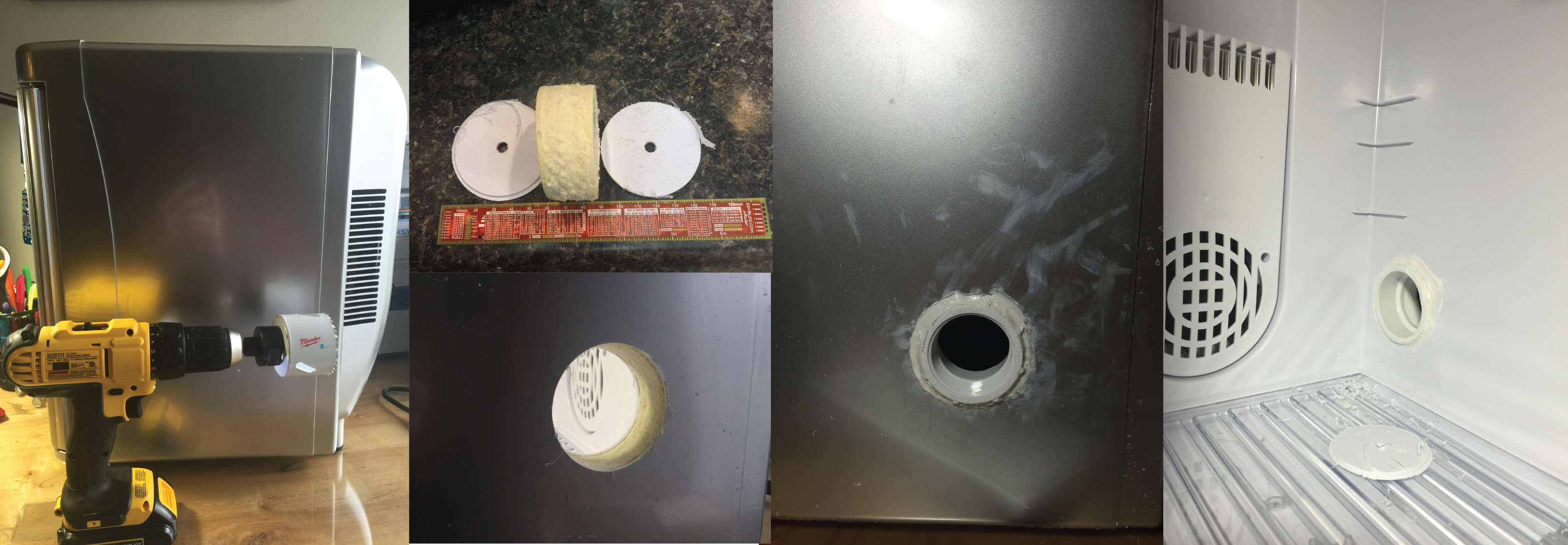
I put the whole thing back together and put a sensor in to monitor the environment and tested again. This time I tried a few different set points with and without containers of water inside the chamber. First with nothing but the sensor setup inside:
For both heating and cooling the performance under no thermal load (other than the sensor electronics) was pretty good. Cooling is rather slow and more poorly controlled than heating though.
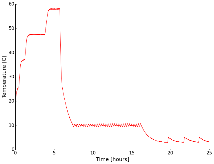
Next I put sealed containers of water on the shelves of the chamber to add some thermal mass and see if that changed the characteristics of the chamber any. It did slow the temperature change as expected, but appears to have had little other effect (I didn't wait long enough for stabilization on some settings).
With a water load the chamber had similar performance, but was slower in getting to temperature as expected.
It looks like at temperatures above ambient the chamber has a stability of +/- 1 degree. Below ambient it becomes a couple of degrees. The absolute reading drifts a bit too. Setting the chamber to a given reading always resulted in stabilization within about a degree of the setting though.
I think this will be a nice addition to my home lab. While the unit isn't incredibly accurate, I will be recording the device temperature anyway, so that works for me. It'd be nice to cool down more quickly though, so I may facilitate that with some dry ice. Stay tuned as I'll be testing instruments in there sometime in the next month or so.
P.S. - The LED light still flickers in a way that indicates unstable power/connection. Not a deal breaker for me since I don't really need the light, but something to remember.
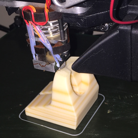
A little over a year ago I got a 3D printer. I've had a great experience with it! I had printed a lot of lab hardware and some fun things, but then let it sit around for a few months while things were very busy in other parts of work. This past week was maker week in State College, so there were lots of 3D printing demonstrations around town and other maker projects. I decided I should get things fired up again. I've got a couple of new projects that will need custom enclosures built. Without being able to have a spot-welder in my apartment, I'm pretty much limited to plastics or paying for the manufacturing.
I re-leveled and calibrated the bed and z-axis mechanism. I carefully re-checked the extruder calibration to be sure that I got the appropriate amount of plastic extruded. Everything looked great, so I downloaded a simple, but utilitarian part for my Apple Watch off thingiverse. Using Slic3r, I created the GCode and sent it off to print. Everything started off like normal, so I left the printer running to deal with other tasks. I came back later and too many surprise the part had stripes!
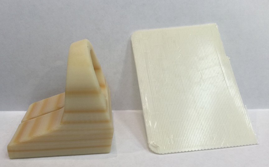
I've always printed with ABS plastic. It's not that I don't want to use PLA, it's just what I've always had on hand and what I know how to work with. I happened to have left the white roll of plastic on the printer after my last print. Since my printer sits next to the window, it gets some sunlight, especially in the morning hours. Not the best location, but it's the only location I can place it for the moment. It looks like the UV radiation has damaged my filament! Every time the part of the roll that was exposed heavily comes around, I get a band. For a simple charging stand, I'm not too upset. I could even try some of the ABS bleaching brews used by antique computer collectors. I may just paint the whole thing with paint that matches my wooden night stand. Maybe this will give me a false wood grain look?
I wanted to confirm that the stripes corresponded to a revolution of the spool. The whole part is darker than parts printed from the same roll months ago, but I'd guess the darker bits were on the top of the roll. By analyzing the GCode that produced the part, I calculated that the printed used about 5.1 meters of filament (<$2). The roll has been used down to a coiling diameter of about 150 mm. That means I expect about 10-11 turns of the reel for the print. I see 7-10 layers depending on what I count, so I'll call that close enough.
Well that's the story for now. Don't leave your ABS in the sunlight, even on your machine. I've been meaning to get a dust cover for the machine and this is even more reason to do so and make sure it's opaque.
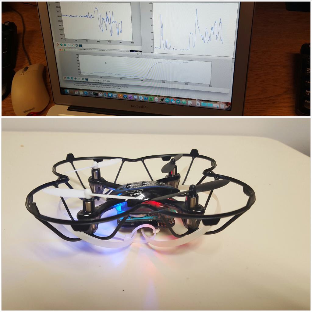
Again we have a short project post in-between the posts of the open science series (part 3 coming soon)! This time I want to share a fun little project involving cheap drones and an instrument pack that I designed on top of the Light Blue Bean module. The pack uses an HTU21D temperature/humidity sensor and a BME180 pressure sensor. I designed the board in the open-source PCB/EDA tool KiCAD. Should you want to reproduce the boards, the files to send off to a board house are available on a GitHub repository here.
I designed the pack to be a measurement device for a home, truck, or airplane of the weather enthusiast or storm chaser. Ideally it will send the data to a smartphone/tablet that then sends it out to the web or lets you do whatever you want with it. It was also a good excuse to play with the bean after hearing about it. While delivering another product to a friend, we decided to strap this sensor to a small and cheap ($33) drone and see what happened. We got some vague data, but the drone didn't get over a few meters high due to the high load. Zip ties provided some protection on takeoff/landing.
Our initial test flight with some quick plots in the background.
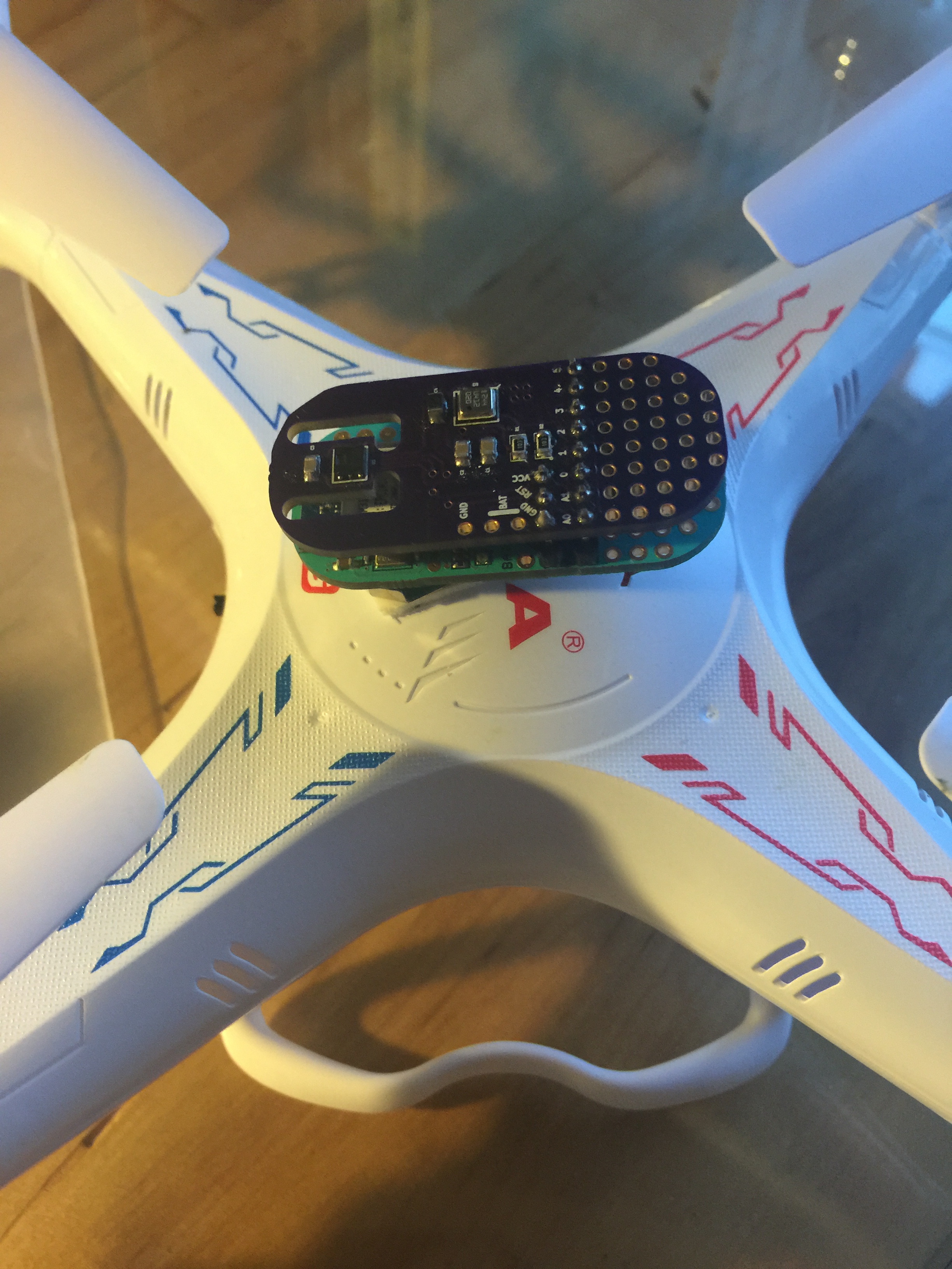
After playing we though it would be fun to do this on a drone with some more power. I grabbed a $55 drone (Syma X5C) on eBay and gave it a shot. After a couple of test flights I just couldn't get the bluetooth link to stay connected at the distances I wanted (50m).
My breakout and the bean attached to the top of the drone body.
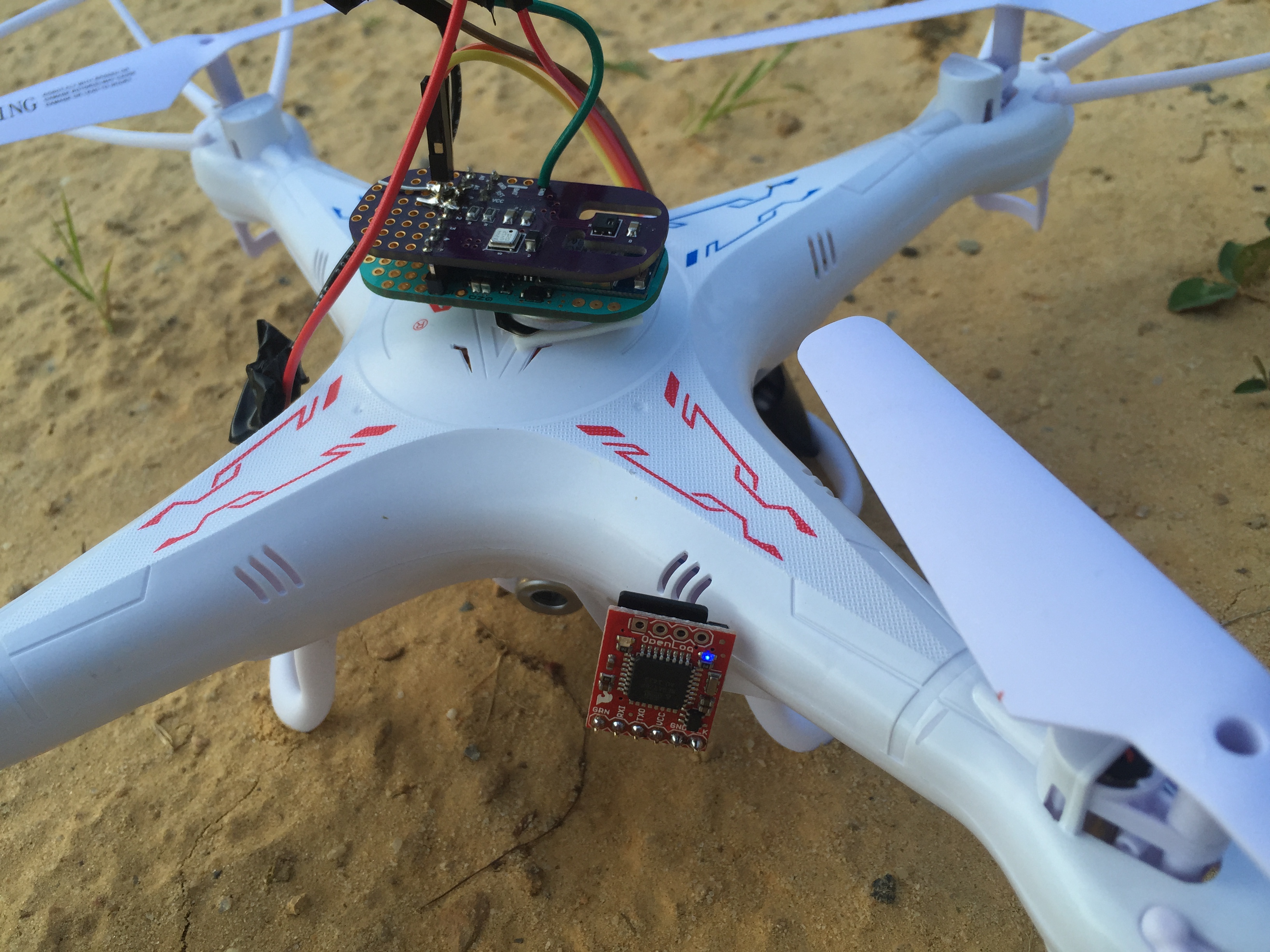
I added a kludge that wrote data to an SD card using the OpenLog. It was extra weight since I needed two more coin cell batteries, but the drone turned out to be able to carry it to 45 m once or twice. Then the drone looses signal and shakily falls out of the sky until I can get control again. While inspiring me to drool over more advanced drones, I did get some interesting data! Some of the plots are rather small in web-view, but click on them to expand. I just didn't want a bunch of individual figures making the post scroll forever.
First I'll show my first SD logged flight(s). Below is the altitude plot (derived from the barometric pressure sensor on-board).
A few up/down flights of the drone. The ascent in the grey box will be examined in detail.
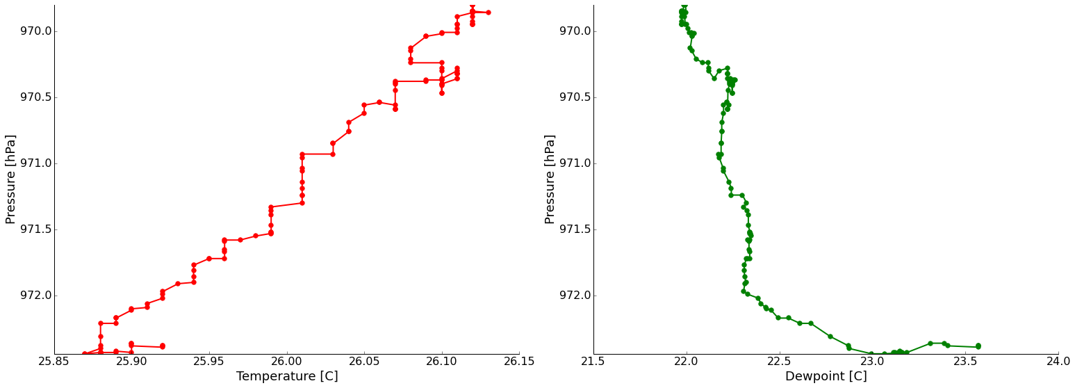
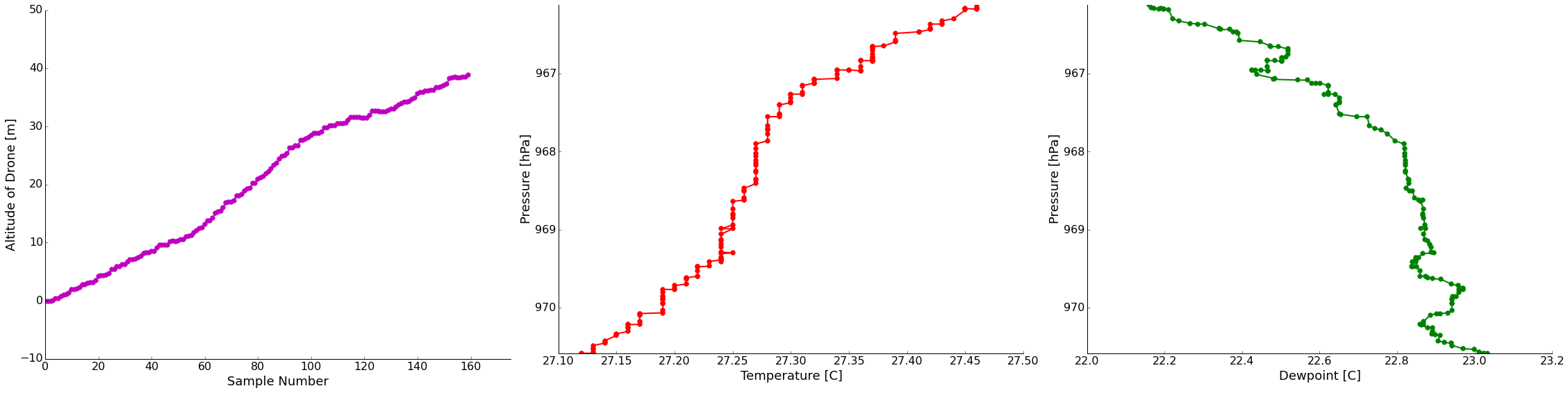
If we take the highest and most constant climb rate ascent (gray box) and look at the temperature/dewpoint data we see rather clean results!
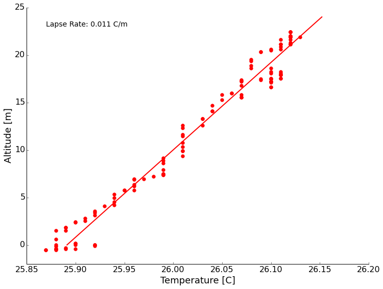
It was a dead still evening, just before sundown. Without any mechanical mixing, we see radiation from the ground producing a temperature inversion (temperature increases with height here). We also see a nice dew point trend to drier air as we ascend. For fun, I calculated the lapse rate. This just means how fast the temperature changes with height. Plotting the data and fitting a line we get about +11 degrees/kilometer of height. A reasonable number. (Perhaps coincidentally about the negative of the typical dry adiabatic lapse rate? It's been too long and I didn't ever do much near ground meteorology. Thoughts appreciated.)
The next evening, a very similar setup without wind, I did another sounding that got up to 45 meters. On this flight I noticed that the bumps in the temperature and dew point trends match rather well with the bump in my ascent rate. Since this drone isn't programmable, I do this by hand which is tricky to judge. It probably has to do with the sensors needing a lot of settling time to equilibrate to their surroundings (a couple of seconds). Maybe flying small circles on the way up is a solution. I also have the video from this flight if you're curious what it looks like. Nothing too interesting, but the uncontrolled descents are rather exciting. I've read about hacking better antennas on this drone for more range, so that's a thought. Before I get it much further away I want to do it in a large field to decrease the risk from a runaway drone. If this proves to be interesting enough, maybe a drone update will be in order. They are pricey though!
This year at the fall meeting of the American Geophysical Union, I presented an education abstract in addition to my normal science content. In this talk, I wanted to raise the awareness of how easy it is to work with electronics and collect geoscience relevant data. This post is here to provide anyone that was at the talk, or anyone interested, with the content, links, and resources!
Sensors and microcontrollers and coming down in price thanks to mass production and advances in process technology. This means that it is now incredibly cheap to collect both education and research grade data. Combine this with the emergence of the "Internet of Things" (IoT), and it makes an ideal setup for educators and scientists. To demonstrate this, we setup a small three-axis magnetometer to measure the Earth's magnetic field and connected it to the internet through data.sparkfun.com. I really think that involving students in the data collection process is important. Not only do they realize that instruments aren't black boxes, that errors are real, and that data is messy, but they become attached to the data. When a student collects the data themselves, they are much more likely to explore and be involved with it than if the instructor hands them a "pre-built" data set.
For more information, watch the 5-minute talk (screencast below) and checkout the links is the resources section. As always, email, comments, etc are welcome and encouraged!