Tag Archives: fluxgate

Fluxgate Magnetometer Wrap-Up (For now)

Per lots of emails and requests I’m going to post what I have from the design of the fluxgate magnetometer mentioned in several previous posts (like this one).  The schematic attached at the bottom is a rough draft, but should provide some guidelines for designing and building a version of this instrument.  I’ve also attached links to several PDFs that I found very helpful when building this demo.

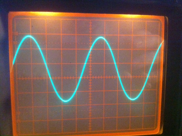
It should be noted that this design doesn’t have a plain readout with XXXXXX nT magnetic field, but displays a waveform on the oscilloscope.  Could one be made? Absolutely! Since this was more of a demonstration of the underlying physics I didn’t bother, but it would be a good weekend project.

First off let me list a few things I would build differently were I building this again:

-       Use shielded lead wires to reduce crosstalk to the coil.

-       Use a simple Analog-to-Digital converter so this output is projected from a laptop to the classroom screen (much easier than gathering students around an oscilloscope).  I think an Arduino might do the trick.  Raspberry Pi would be a good choice too.

-       Add gain adjustment knobs to the control panel.

-       I would again use the Velleman kit for the signal generator instead of re-designing the wheel.

When using this in the classroom I laid it alongside commercial magnetometers on the table.  We discussed the physical principles behind the instrument, and then students would use the demo fluxgate to generate an output wave.  Afterwards we used the commercial magnetometers to do simple tasks like finding conduits and keys. 

It would also be nice to have a first-principles proton-precession magnetometer.  There is a book “Signals from the Subatomic World: How to Build a Proton PrecessionMagnetometer” that describes one such instrument, but significant improvements in the instrument could be made with modern programming languages and ADC devices. 

I still welcome questions on the fluxgate and will probably update the instrument next time I teach an Intro Geophysics course (undetermined).  Thank you for all the interest and if you build one, please send your results and we’ll put them up here for all to benefit.  

Building a Fluxgate Magnetometer Part 2

With school starting progress has slowed some, but currently most of the system is constructed.  First off the sense coil had to be finished.  The wire ends were coated in fingernail polish to keep the coil from slowly working undone and the entire setup was placed into a clear acrylic tube to protect it from wear.  The tube was stopped with standard rubber plugs and a computer power cord was soldered on for connection purposes.

With the function generator working it was time to amplify its ~100mV output to something that would induce a larger field via the driver coil.  Finally I decided to go with an operational amplifier (op-amp) design.  This requires both a positive and negative voltage source which is easily accomplished with two 9V batteries.  The signal generator will be run off a third battery because it is crucial that the two op-amp supply batteries remain at equal voltages.  My initial breadboard design (below) clipped the waveform badly (also below).  After some readjustments and gain fiddling a nice waveform was reached.  I built two amplifiers on a perf-board (one to amplify the signal to the driver coil and one to amplify the signal coming back from the sense coil).

It was also time to being thinking about a case/display.  Lexan seemed like the obvious choice so students can see inside.  I bought 2 sheets of lexan and nylon hardware to separate them.  Leaving the sides open allows easy oscilloscope probe access for recalibrating the amplifiers (I left little copper connections on the board for this purpose).  I designed the front control panel (not implemented yet) and drilled all the holes required.  Finally after mounting all the boards down to the lexan I powered up the amplifiers and they worked great (below)!

Next the bandpass filter needs to be nailed down.  I've worked on it some, but cannot get a satisfactory result to build up onto the last perf-board.  The signal that carries the information we are interested in is the 2nd harmonic of the 1kHz driver signal.  It will be weak so it is likely that the amplifier will need a bit of reworking and hopefully I can build some gain into the bandpass design (also op-amp).  The classic catch is increasing the Q of the filter, but killing the amplitude of the signal.  More to come...

Building a Fluxgate Magnetometer - Part 1 (and NASA)

Today I want to discuss the first steps in building a simple fluxgate magnetometer for a classroom demonstrator.  Originally this post was going to be a wrap up of NASA work and the magnetometer would come later, but I'm still waiting on my presentation to clear export control so I can post it.  As soon as it does, I'll put it up along with a short article.

This semester I'll be the TA for 'Global Geophysics', mostly doing lab instruction/writing.  After some thought I decided that students need more hands-on classroom geophysics, which is difficult to do.  By its nature geophysics is an outdoor activity with normally expensive instruments.  The instruments are often viewed as a mysterious black box that spits out numbers used to make a map.  This must change.  With a proper understanding of the instruments students will better understand errors in the data, how to troubleshoot in the field, and know why certain hardware limits exist.

The concept of a fluxgate magnetometer is pretty simple.  Rather than go into detail I'll refer you to this wikipedia article.  This is mainly to chronicle the construction so others can reproduce this (assuming we get a working model).  My design came from a physics lab at Brown University.  The instructions were vague in parts and I'll be taking some liberties as we go along.  This first article will cover construction of the coil and the driver circuit.

The fluxgate coil consists of a driver coil surrounding a soft steel wire, and a secondary coil to pickup signal surrounding the primary coil.  First I took 16ga annealed steel wire from Lowes and cut it to about 1m long, cleaned it, and made it as straight as possible.  Afterwards I wrapped close to 2000 turns of 22ga magnet wire (Radio Shack #278-1345) tightly along its length.  This was then bent in half making a 'U' and that was wrapped with close to 1000 turns of 26ga magnet wire. I used large wire because it will be more durable and I used different gauge wire since the enamel insulation was a different color allowing students to easily see the windings.

That's all there is to the coil.  To increase durability I will probably clear coat the coil and place it into a small acrylic tube so its difficult to bend or break.  The next step is to build a driver for the primary coil.  The Brown lab used a function generator.  Currently I don't have one, nor have I found a suitable cheap unit.  This meant improvising, and luckily Velleman makes a signal generator kit that is just about right.  It operates at 1kHz (the desired frequency for this project) and produces sine, square, triangle, and integrator waves.  The kit was pretty easy to build in just about an hour and works well as seen by the oscilloscope output below, but frequency stability is not phenomenal (especially when then unit is cold).  

Next a few amplifiers need to be designed and built.  The signal generator kit cannot pull the load of the coil, so a simple +/- 9V system will probably do.  The output will also need some kind of amplification.  The lab I found also uses a bandpass filter.  Once the amplifiers are working it will be time to decide if this is necessary and if I want to use an oscilloscope and hardware filters, or an ADC and display the waveform on a computer projector using software filters.