Category Archives: Machining

Fix What Bugs You (aka Lean) - Tool post wrench

Awhile back I was listening to Episode 101 of The Productivity Show in which Paul Akers of FastCap was being interviewed about lean. Lean is one of those buzz words that gets thrown around without much thought, but he explained it in a simple way that the marketers would never approve of and some would argue is just common sense. Paul said lean means that you should "fix what bugs you". While many of us do that already, I've tried to keep that mantra going as I've been working on projects or just going through daily life. That coffee container that I hated dealing with every morning because it was slow? Gone and replaced with a fast open/close sealed container. That one annoying error message on my laptop I've been closing out every time I boot up for the last year? 15 minutes with google and I'll never click it again. These are all little examples of realizing that something was, and had been, annoying me and stopping what I was doing to fix it. Paul talks about this idea some in a video (below), but I wanted to share an example of a recent thing that bugged me and I fixed with about an hour's worth of effort.

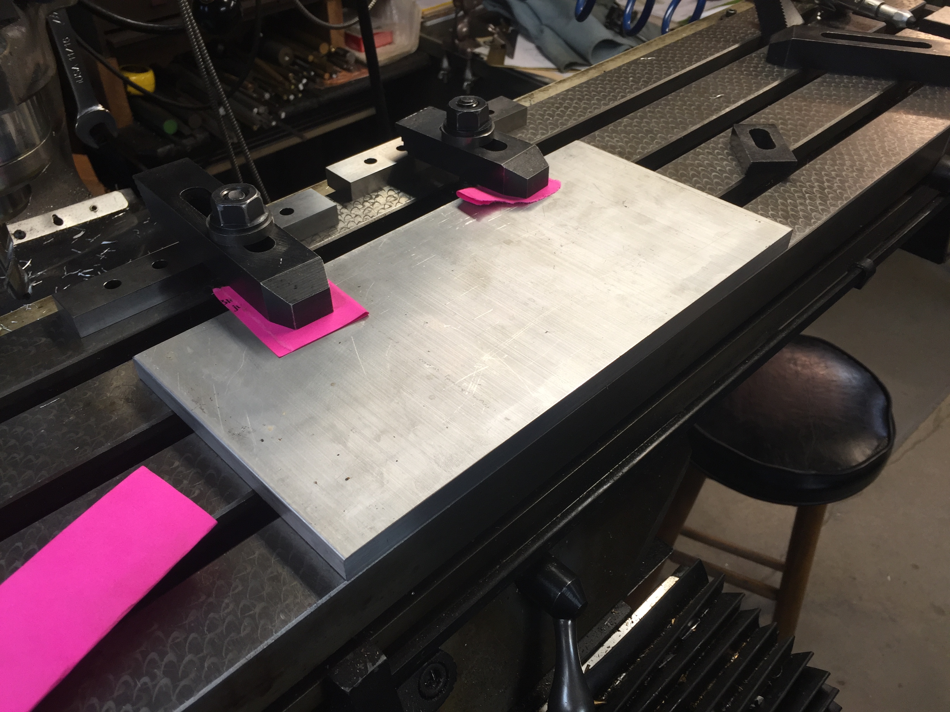
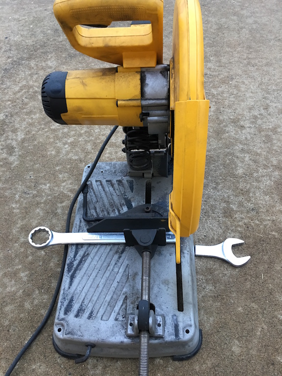
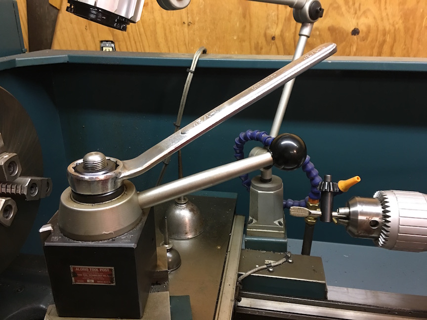
When I'm using tools, I want to be efficient. I want to have the right tool for the right job and do the job well. Recently I was using a lathe to make some parts and noticed that they had been using a large crescent wrench to adjust the tool post  on the machine. The wrench was about 2 feet long and was heavy. Not only that, it encouraged over tightening of the nut with its excess mechanical advantage. Every time I changed the tool post, I pulled out the big wrench and carefully adjusted things. This got old very quickly.

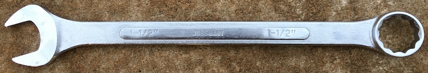
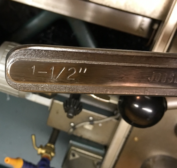
I stopped into Tractor Supply Company and bought a 1.5" combination wrench for $15. I took the wrench back to the shop and put it on the adjustment nut. It was still a bit long and interfered with the lever on the tool post lock, so I still wasn't very happy. For $15, I decided it was time to fix this problem once and for all.

First I got out the chop saw and sawed off the open end that I didn't need. This took just a few seconds and already had the handle at a more suitable length.

Next, I grabbed the torch and heated the tool until I could bend the wrench so that the handle was at an angle. It took a few trips across the shop, trying the wrench on the machine, to get the angle just right.

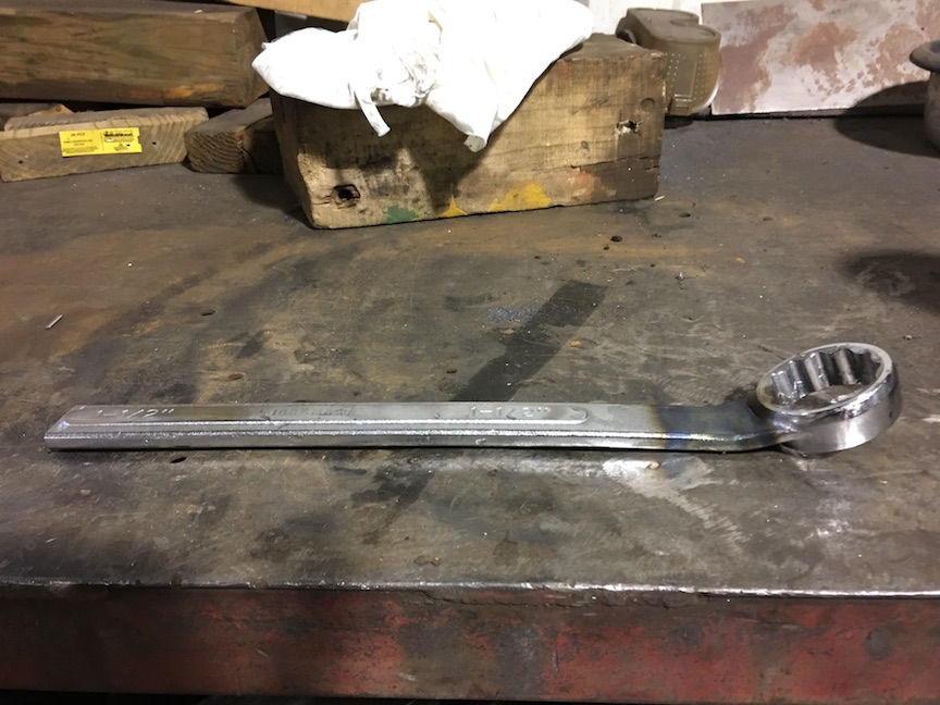
I could have stopped, but I wanted to have a nice rounded handle end that was smooth to slide your hand off and wouldn't scratch the back of your hand if you brushed against it. After some grinding, filing, and emery paper work I had a really nice smoothed surface. A bit of time on the wire wheel cleaned up discoloration where I had heated the tool.

And with less than an hour's worth of time, I had a nice little tool to set the tool post. Now I'm less resistant to readjusting and therefore can make better parts faster. Lazy? Maybe, but it sure is nice to not dislike the tool and I've made it harder to make a goof like over tightening.

Is this rocket science? No. In fact, Keith Fenner has done this as well (video below). The point is, look around and find a few things this week that bug you and take 5-60 minutes and fix them. The time and frustration saved will be worth it!

Squeezing Rocks with your Bare Hands

Our lab group. Photo: Chris Marone

Our lab demo group. Photo: Chris Marone

As frequent readers of the blog or listeners of the podcast will know, I really like doing outreach activities. It's one thing to do meaningful science, but another entirely to be able to share that science with the people that paid for it (taxpayers generally) and show them why what we do matters. Outreach is also a great way to get young people interested in STEAM (Science, Technology, Engineering, Art, Math). When anyone you are talking to, adult or child, gets a concept that they never understood before, the lightbulb going on is obvious and very rewarding.

Our lab group recently participated in two outreach events. I've shared about the demonstrations we commonly use before when talking about a local science fair. There are a few that probably deserve their own videos or posts, but I wanted to share one in particular that I improved upon greatly this year: Squeezing Rocks.

Awhile back I shared a video that explained how rocks are like springs. The normal demonstration we used was a granite block with strain gauges on it and a strip chart recorder... yes... with paper and pen. I thought showing lab visitors such an old piece of technology was a bit ironic after they had just heard about our lab being one of the most advanced in the world. Indeed when I started the paper feed, a few parents would chuckle at recognizing the equipment from decades ago. For the video I made an on-screen chart recorder with an Arduino. That was better, but I felt there had to be a better way yet. Young children didn't really understand graphs or time series yet. Other than making the line wiggle, they didn't really get the idea that it represented the rock deforming as they stepped on it or squeezed it.

I decided to go semi old-school with a giant analog meter to show how much the rock was deformed. I wanted to avoid a lot of analog electronics as they always get finicky to setup, so I elected to go with the solution on a chip route with a micro-controller and the HX711 load cell amplifier/digitizer. For the giant meter, I didn't think building an actual meter movement was very practical, but a servo and plexiglass setup should work.

A very early test of the meters shows it's 3D printed servo holder inside and the electronics trailing behind.

A very early test of the meters shows it's 3D printed servo holder inside and the electronics trailing behind.

Another thing I wanted to change was the rock we use for the demo. The large granite bar you stepped on was bulky and hard to transport. I also though squeezing with your hands would add to the effect. We had a small cube of granite about 2" on a side cut with a  water jet, then ground smooth. The machine shop milled out a 1/4" deep recess where I could epoxy the strain gauges.

Placing strain gauges under a magnifier with tweezers and epoxy.

Placing strain gauges under a magnifier with tweezers and epoxy.

Going into step-by-step build instructions is something I'm working on over at the project's Hack-a-Day page. I'm also getting the code and drawings together in a GitHub repository (slowly since it is job application time). Currently the instructions are lacking somewhat, but stay tuned. Checkout the video of the final product working below:

The demo was a great success. We debuted it at the AGU Exploration Station event. Penn State even wrote up a nice little article about our group. Parents and kids were amazed that they could deform the rock, and even more amazed when I told them that full scale on the meter was about 0.5µm of deformation. In other words they had compressed the rock about 1/40 the width of a single human hair.

A few lessons came out of this. Shipping an acrylic box is a bad idea. The meter was cracked on the side in return shipping. The damage is reparable, but I'm going to build a smaller (~12-18") unit with a wood frame and back and acrylic for the front panel. I also had a problem with parts breaking off the PCB in shipment. I wanted the electronics exposed for people to see, but maybe a clear case is best instead of open. I may try open one more time with a better case on it for transport. The final lesson was just how hard on equipment young kids can be. We had some enthusiastic rock squeezers, and by the end of the day the insulation on the wires to the rock was starting to crack. I'm still not sure what the best way to deal with this is, but I'm going to try a jacketed cable for starters.

Keep an eye on the project page for updates and if any big changes are made, you'll see them here on the blog as well. I'm still thinking of ways to improve this demo and a few others, but this was a giant step forward. Kids seeing a big "Rock Squeeze O Meter" was a real attention getter.

Hmm... As I'm writing this I'm thinking about a giant LED bar graph. It's easy to transport and kind of like those test your strength games at the fair... I think I better go parts shopping.

Mill Time - Back in the Shop

While home for the holidays, I decided to make a little calibration stand that I need for a tilt meter project I'm working on. Back in the 2006 time frame I had worked to learn basic machining skills on the mill and lathe. I never was amazing at it, but managed to get a basic skill set down. I ended up back over at my mentor's shop this week to make a simple part, but thought you may enjoy seeing some photos of a simple milling setup.

The first step is to have a part design that is exactly what you want to make. Problems always arise when you have a rough sketch and make it up as you go. For some hobby projects that can work, but as our systems become more and more complex, it generally just leads to wasted time, material, and lots of frustration. This particular part is exceedingly simple, but I went ahead and made a full 3D CAD model anyway, just to illustrate the process.

Our goal is to make a flat plate for a tilt meter to set on. We will then elevate one end of the plate a known amount with precision thickness pieces of metal called gauge blocks. Knowing the distance between the ends of the plate and the amount we elevate one end, we can very accurately calculate the angle. That lets me calibrate the readings from the tilt meter to real physical units of degrees or radians. All good designs start with a specification, my specification was I wanted at least 5 different tilts ranging from 0 - 0.5 degrees, the more combinations possible the better. I also wanted a compact and rigid device that wouldn't bend, warp, or otherwise become less accurate when tilted.

Time to fire up a Jupyter notebook and do some calculations! I mainly wanted to be able to play with the tradeoffs of baseline length, height of gauge block (they come in standard sizes), etc. After playing with the numbers some, I came with up a design that used multiple baseline lengths with available gauge blocks. I decided to use ball bearings under the plate to give nice point contacts with the surface of the table as well. This meant I needed a plate about 6" x 12" with hemispherical divots to retain the bearings.

Next, I fired up FreeCAD and made the design by taking a 6" x 6" plate and using 0.5" spheres as the cutting shape to make the divots. The divots are only 1/8" deep, so setting them in 1/4" from the edges is enough. Then I just mirrored that 6" x 6" part to make the full part. This lets me tilt both directions the same amount without turning or moving the instrument under test. The drawing I produced is shown in both bottom and oblique view.

bottom oblique

Next it was time to make the plate. I ended up with a piece of 0.5" thick 6061 Aluminum plate. We first cut it to roughly the size we wanted (slightly oversized) with a bandsaw. Then the plate was clamped down to the milling machine table to take off the extra material with a milling bit and give the sides a nice and clean finish. We ended up re-clamping during the work (almost always a bad idea) and had a slight taper on the width, but that isn't a concern for the usefulness. (By slight taper I mean about 20 thou along the length.)

We then were ready to make the divots. To do this we used a ball end mill that makes nice hemispheres. This is a very simple part, so just finding the edge, setting the readout, and doing the cuts took about 20 minutes. I've included some photos incase you haven't seen a milling setup before. It's really great fun to be able to control these cutters and tools to a thousandth of an inch and sculpt metal into what you need. As I said, this isn't a complex part, but that's good because I was a little rusty!

2015-12-30 10.15.19 2015-12-30 10.51.59

In the end we got a nice plate and I think it will perform its duty very well. I'll most likely write a future post showing it in use and explaining instrument calibration. I've included some pictures of the finished plate and how it will work sitting on the ball bearings.

2015-12-30 15.45.32

2015-12-30 15.46.50

Until next time, have a happy and safe new year!