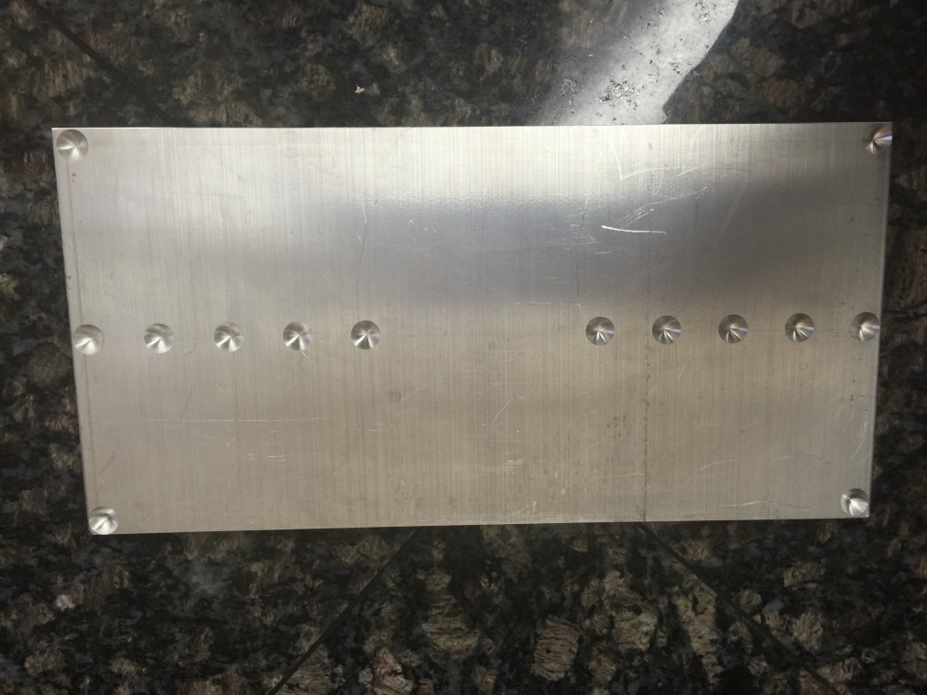
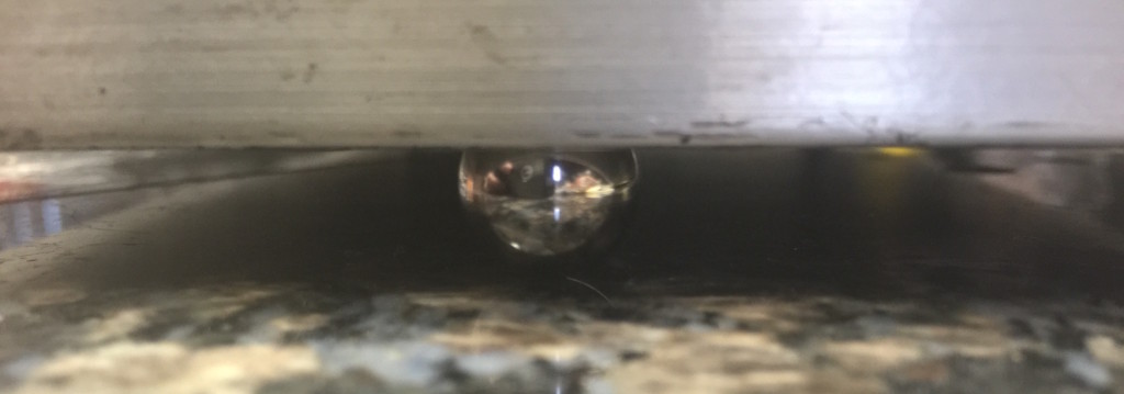
While home for the holidays, I decided to make a little calibration stand that I need for a tilt meter project I'm working on. Back in the 2006 time frame I had worked to learn basic machining skills on the mill and lathe. I never was amazing at it, but managed to get a basic skill set down. I ended up back over at my mentor's shop this week to make a simple part, but thought you may enjoy seeing some photos of a simple milling setup.
The first step is to have a part design that is exactly what you want to make. Problems always arise when you have a rough sketch and make it up as you go. For some hobby projects that can work, but as our systems become more and more complex, it generally just leads to wasted time, material, and lots of frustration. This particular part is exceedingly simple, but I went ahead and made a full 3D CAD model anyway, just to illustrate the process.
Our goal is to make a flat plate for a tilt meter to set on. We will then elevate one end of the plate a known amount with precision thickness pieces of metal called gauge blocks. Knowing the distance between the ends of the plate and the amount we elevate one end, we can very accurately calculate the angle. That lets me calibrate the readings from the tilt meter to real physical units of degrees or radians. All good designs start with a specification, my specification was I wanted at least 5 different tilts ranging from 0 - 0.5 degrees, the more combinations possible the better. I also wanted a compact and rigid device that wouldn't bend, warp, or otherwise become less accurate when tilted.
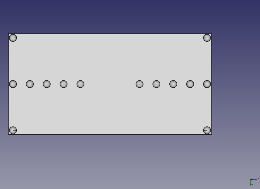
Time to fire up a Jupyter notebook and do some calculations! I mainly wanted to be able to play with the tradeoffs of baseline length, height of gauge block (they come in standard sizes), etc. After playing with the numbers some, I came with up a design that used multiple baseline lengths with available gauge blocks. I decided to use ball bearings under the plate to give nice point contacts with the surface of the table as well. This meant I needed a plate about 6" x 12" with hemispherical divots to retain the bearings.
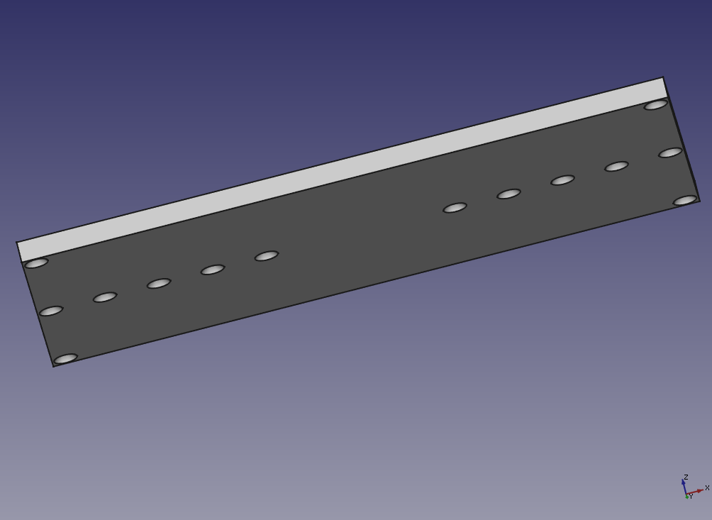
Next, I fired up FreeCAD and made the design by taking a 6" x 6" plate and using 0.5" spheres as the cutting shape to make the divots. The divots are only 1/8" deep, so setting them in 1/4" from the edges is enough. Then I just mirrored that 6" x 6" part to make the full part. This lets me tilt both directions the same amount without turning or moving the instrument under test. The drawing I produced is shown in both bottom and oblique view.
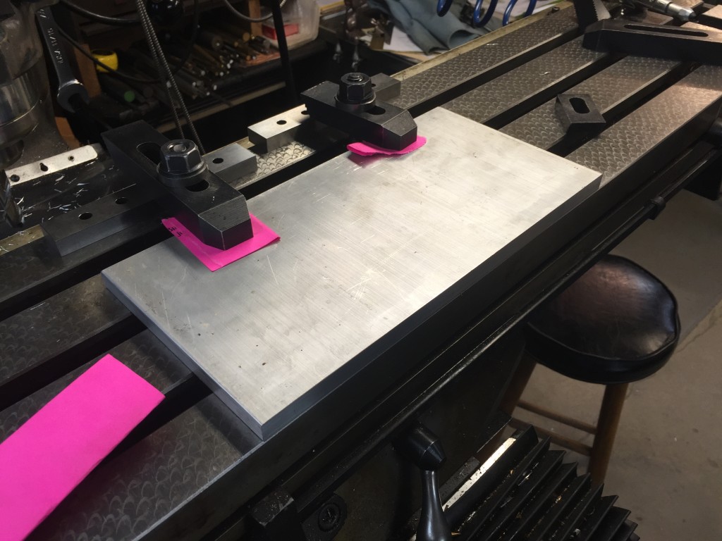
Next it was time to make the plate. I ended up with a piece of 0.5" thick 6061 Aluminum plate. We first cut it to roughly the size we wanted (slightly oversized) with a bandsaw. Then the plate was clamped down to the milling machine table to take off the extra material with a milling bit and give the sides a nice and clean finish. We ended up re-clamping during the work (almost always a bad idea) and had a slight taper on the width, but that isn't a concern for the usefulness. (By slight taper I mean about 20 thou along the length.)
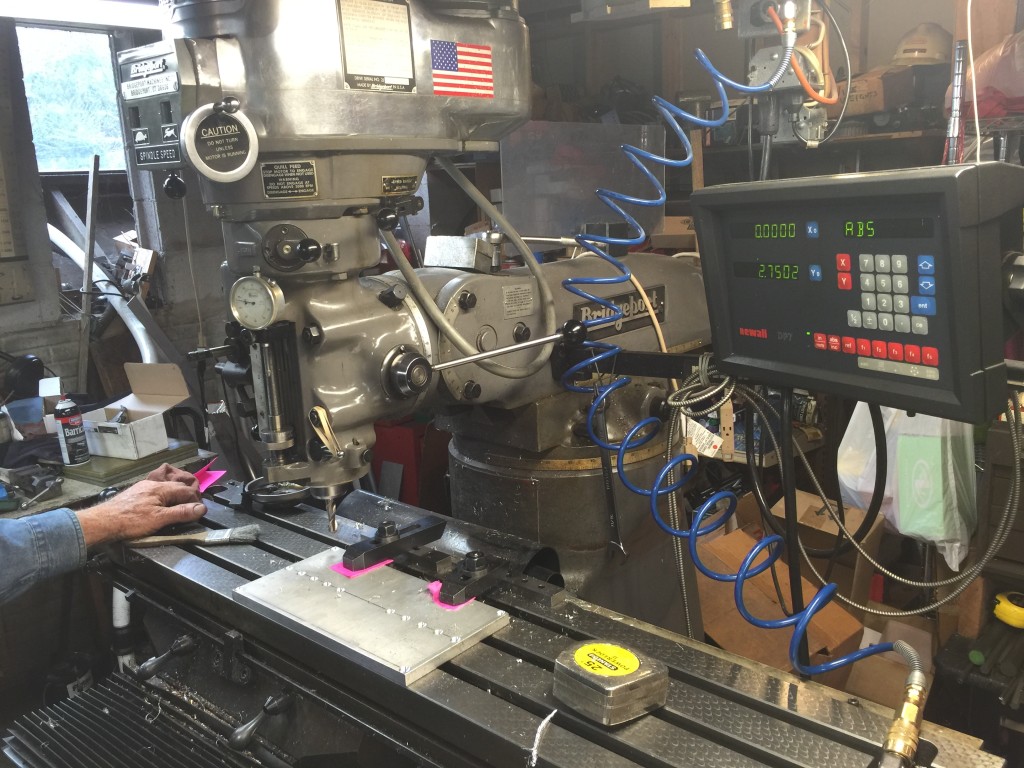
We then were ready to make the divots. To do this we used a ball end mill that makes nice hemispheres. This is a very simple part, so just finding the edge, setting the readout, and doing the cuts took about 20 minutes. I've included some photos incase you haven't seen a milling setup before. It's really great fun to be able to control these cutters and tools to a thousandth of an inch and sculpt metal into what you need. As I said, this isn't a complex part, but that's good because I was a little rusty!
In the end we got a nice plate and I think it will perform its duty very well. I'll most likely write a future post showing it in use and explaining instrument calibration. I've included some pictures of the finished plate and how it will work sitting on the ball bearings.
Until next time, have a happy and safe new year!

